
Linear motor motion control method based on fixed-step speed measurement

A speed measurement, linear motor technology, applied in the direction of motor generator control, control system, electrical components, etc., can solve the problems of limited application of grating scale, difficult manufacturing, and high requirements for working conditions, so as to reduce system complexity and system cost. Effect

Active Publication Date: 2010-09-22
湖南天安门业科技有限公司
View PDF5 Cites 22 Cited by
  • Summary
  • Abstract
  • Description
  • Claims
  • Application Information

AI Technical Summary

Problems solved by technology

High-resolution grating scales are generally expensive, difficult to manufacture, and require high working conditions. These characteristics directly limit the application of grating scales in sliding doors.
[0006] In the translational door using linear motors, Japan Tateyama Company only relies on three Hall switch sensors to measure the speed of the linear motor mover, but its products need to be customized, that is, the load cannot be set arbitrarily, which shows that its control method is very important. The model has strict requirements, which is not conducive to the mass development of products

Method used


Image

  • Linear motor motion control method based on fixed-step speed measurement
  • Linear motor motion control method based on fixed-step speed measurement
  • Linear motor motion control method based on fixed-step speed measurement

Examples


Embodiment Construction

[0030] In the method of the present invention, the Hall switch sensor array 2 is composed of Hall switch sensors arranged at equal intervals to measure the position and speed of the mover of the linear motor. Velocity measurements are made at fixed displacement intervals of mover motion. The mover is composed of several magnets 1 . Assuming that the displacement interval for speed measurement is D, and the length of the single magnet 1 is L, the number of Hall switch sensors that should be included in the Hall switch sensor array 2 is L / D+1. Such as image 3 An array arrangement using 13 Hall switch sensors is shown. It corresponds to the case of L=24mm, D=2mm.

[0031] According to the magnetic pole below it, N or S, the Hall switch sensor will output 0 or 1, and the output of the entire array forms a thirteen-bit binary string (b0 b1 b2 b3 b4 b5 b6 b7 b8 b9 b10 b11b12 b13). The hall switch sensor array 2 outputs the coded parity bit as a flag semaphore. The fixed displa...


PUM


Abstract

The invention discloses a linear motor motion control method based on fixed-step speed measurement. Equidistantly arranged Hall switch sensor arrays are used for conducting the position measurement and the speed measurement of the rotor of a linear motor and implementing back-and-forth motion control by stages. The control sequentially comprises a high-speed constant speed stage, a speed reduction stage, a low-speed constant speed stage and a boundary guidance stage. Position PID control, acceleration PID control, speed PID control and position PD control are respectively implemented in each of the four stages. Since the method is based on a simple measurement device and the motion control of the linear motor with variable load capacity can be realized, the invention has the advantages that no grating precise measurement mechanism is required, the problem that the millimeter-scale linear motor positioning control cannot be realized on the dependence of Hall switch sensors only in the prior art is solved, and the cost and the complexity of the system are reduced.

Description

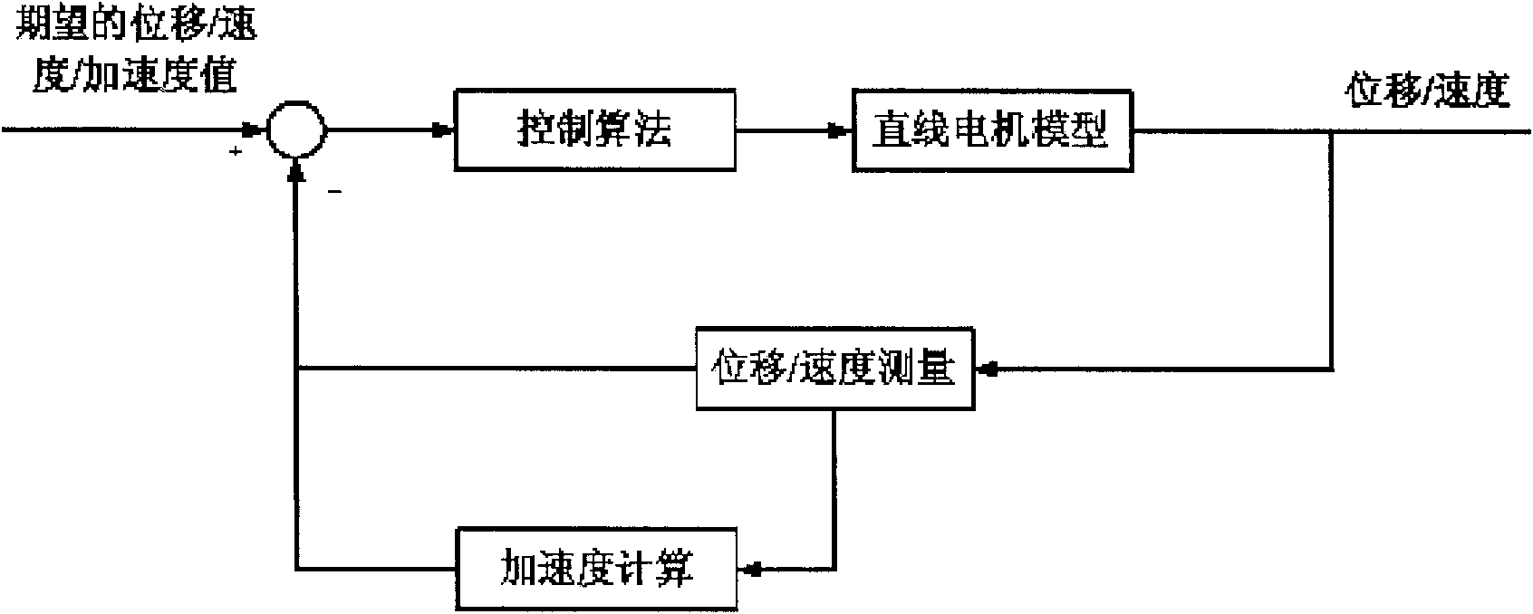
technical field [0001] The invention belongs to a linear motor control method, in particular to a linear motor motion control method based on fixed-step speed measurement. Background technique [0002] The principle of linear motor control is as figure 1 As shown, the central controller generates the control quantity and outputs the control signal according to the result of the detection feedback, and the motor drive module drives the motor to move. When the mover of the linear motor moves, the detection feedback part produces signal changes, which are fed back to the central controller. The central controller adjusts the control of the motor according to the feedback content, so that the linear motor runs smoothly. The control function structure of the linear motor is as follows: figure 2 shown. [0003] The difficulty of linear motor control lies in the particularity of its control model. The linear motor model is nonlinear and can exhibit different main characteristi...

Claims


Application Information

Patent Timeline
IPC IPC(8): H02P8/22
CPCG01R33/0094
Inventor 谢文超韩大鹏
Owner 湖南天安门业科技有限公司
Learn More