Fuel filling device for vehicle fuel tank

一种燃料箱、供油口的技术,应用在供油口装置领域,能够解决开闭器困难、不现实等问题,达到提高交换性、抑制移动、防止对流的效果

Inactive Publication Date: 2012-11-07
HONDA MOTOR CO LTD
View PDF3 Cites 0 Cited by
  • Summary
  • Abstract
  • Description
  • Claims
  • Application Information

AI Technical Summary

Problems solved by technology

However, in motorcycles and other automatic two-wheeled vehicles, due to the layout of the fuel tank, it is unrealistic to install a long oil supply guide cylinder on the fuel tank, so it is actually very difficult to install a shutter such as a car. difficult

Method used


Image

  • Fuel filling device for vehicle fuel tank
  • Fuel filling device for vehicle fuel tank
  • Fuel filling device for vehicle fuel tank

Examples


Embodiment 1

[0047] First, from Figure 1 ~ Figure 4 The description begins with the first embodiment of the present invention shown.

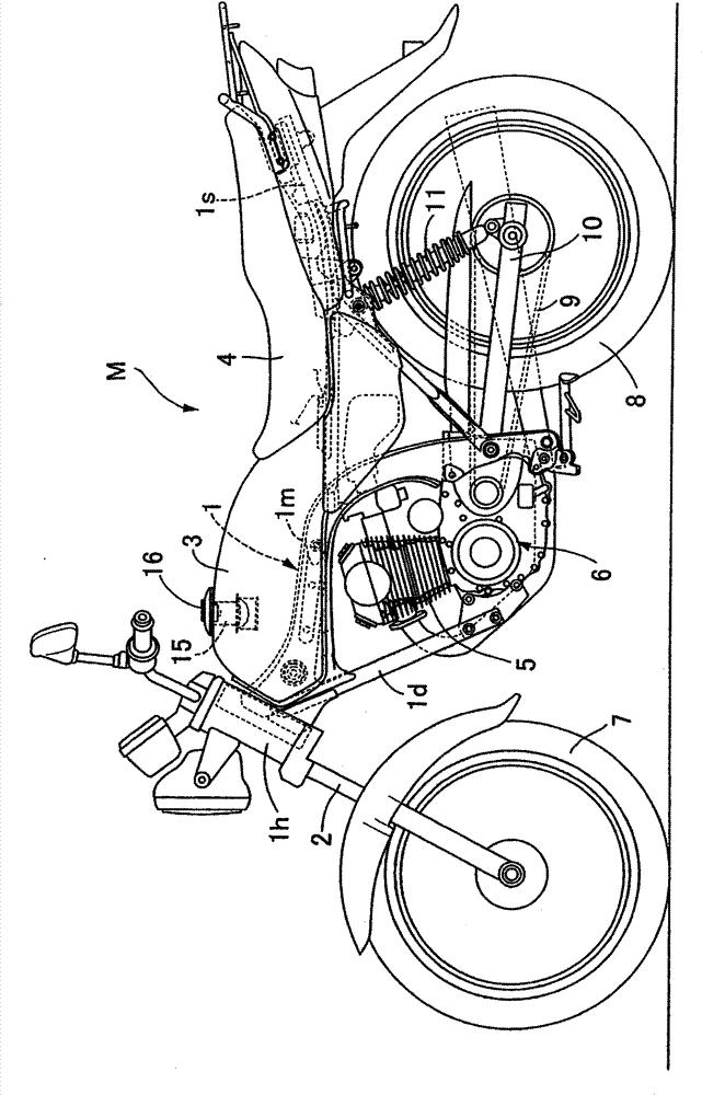
[0048] exist figure 1 Among them, a frame 1 of a motorcycle M includes: a head tube 1h that supports a front fork 2 in a direction that can be steered; The rear end of the horizontal part of the frame 1m extends substantially horizontally to the rear of the seat rail 1s, the frame lower tongue 1d extends obliquely downward from the head pipe 1h, and the fuel tank 3 is attached to the main frame 1m and connected behind it. The arranged seat 4 is attached to the seat rail 1s, and the power unit 6 including the engine 5 arranged directly below the fuel tank 3 is mounted between the lower tongue 1d of the frame and the lower curved portion of the main frame 1m. The front wheel 7 is pivotally supported on the lower end of the front fork 2, and the rear wheel 8 driven by the power unit 6 via the chain 9 is pivotally supported on the rear end of the rear fork 1...

Embodiment 2

[0069] Next, explain Figure 5 and Figure 6 Shown is the second embodiment of the present invention.

[0070] In this second embodiment, a pair of support pieces 22b, 22b are formed at both ends of the two plate members 22, 22 constituting the oil gun stopper 20, and the protrusions 24 of each plate member 22, 22 are , 24 are biased in opposite directions from the axis of the oil supply guide cylinder 15, so that the above two strip plate members 22, 22 are separated from each other, and the respective pair of supporting pieces 22b, 22b are welded to the lower surface of the mounting plate 18 On, other structures are the same as the previous embodiment, therefore, in Figure 5 and Figure 6 In , parts corresponding to those in the previous embodiments are denoted by the same reference numerals, and redundant descriptions are omitted.

[0071] According to this second embodiment, compared with the previous embodiments, although the number of supporting pieces 22b of the st...

Embodiment 3

[0073] Next, in Figure 7 and Figure 8 In the third embodiment of the present invention shown, a pair of two plate members 22, 22 constituting the oil gun stopper 20 of the first embodiment are formed along the inner peripheral surface of the oil supply guide cylinder 15. The supporting pieces 22b, 22b are welded and fixed on the lower inner peripheral surface of the oil supply guide cylinder 15. Other structures are the same as the first embodiment, therefore, in Figure 7 and Figure 8 In FIG. 1, the same reference numerals are assigned to the parts corresponding to those of the first embodiment, and overlapping descriptions will be omitted.

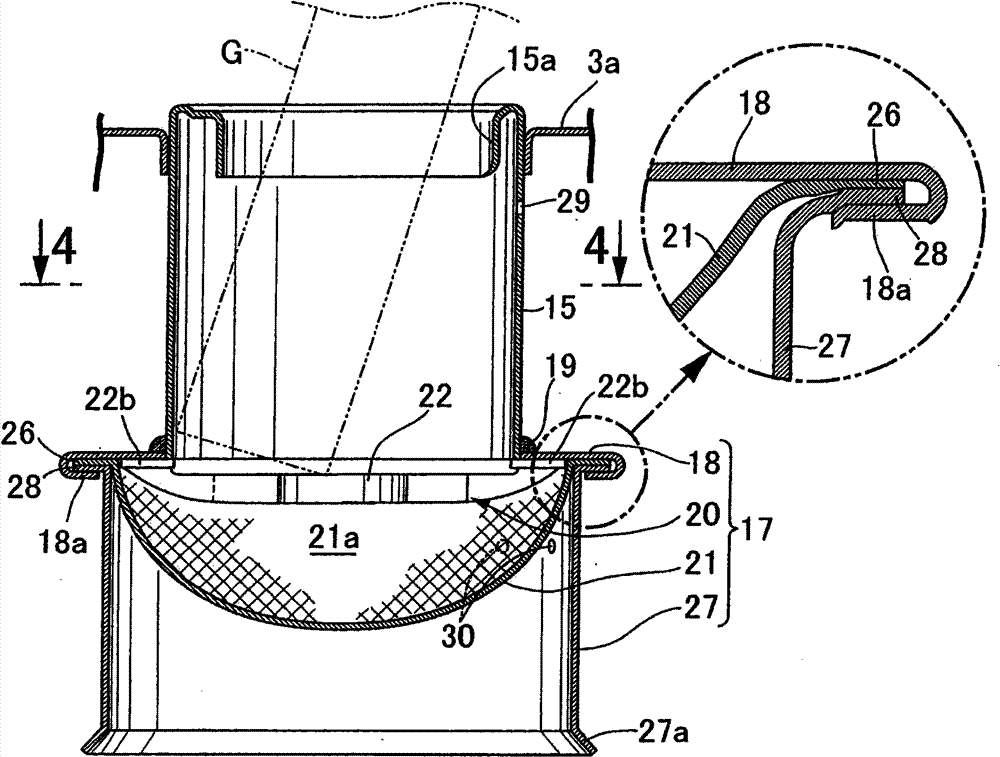
[0074] In the case of the third embodiment, the flame arrester assembly 17 is composed of three of the mounting plate 18 , the flame arrester 21 and the skirt 27 .


PUM


Abstract

A fuel filling device for a vehicle fuel tank has a fuel filling opening (15a) in an upper wall (3a) of a vehicle fuel tank (3) for containing ethanol fuel as engine fuel, and also has a fuel filling guide tube (15) extending from the fuel filling opening (15a) into the fuel tank (3). The fuel filling guide tube (15) has a flame arrester (21) for covering a lower opening of the fuel filling guidetube (15) and permiting flow of fuel while preventing entry of fire. The fuel filling guide tube (15) also has a skirt (27) extending downward from the outer peripheral edge of the flame arrester (21). The skirt (27) prevents convection of air occurring between the fuel tank (3) and the fuel filling guide tube (15) and produced through the flame arrester (21). The flame arrester suppresses entry of fire from the fuel filling opening into the fuel tank and, in addition, prevents movement of ethanol gas from the upper part of the fuel tank to the fuel filling guide tube.

Description

technical field [0001] The present invention relates to a fuel supply port for a vehicle fuel tank in which a fuel supply port and a fuel supply guide tube extending from the fuel supply port into the fuel tank are provided on the upper wall of a fuel tank for a vehicle storing ethanol fuel as fuel for an engine Improvements to the device. Background technique [0002] Recently, research and development of ethanol-fueled vehicles has been extensively carried out. However, in a fuel tank storing ethanol fuel, when the ethanol concentration is approximately 100%, the air-fuel ratio at normal temperature is often in the flammable range. Bringing the fire close to the fuel supply port of the fuel tank for some reason also suppresses the fire from entering the fuel tank. [0003] Usually, in a car, a device such as a switch is provided in the fuel supply guide cylinder extending upward from the fuel tank, which is usually kept in a closed state and opened when the fuel supply g...

Claims


Application Information

Patent Timeline
Patent Type & Authority Patents(China)
IPC IPC(8): B62J35/00B60K15/04
CPCB62J35/00
Inventor 武藤裕辅与仓康文国府志朗
Owner HONDA MOTOR CO LTD
Why Eureka
Try Eureka