Power supply circuit and display device including same

A technology of power supply circuits and power terminals, which is applied to output power conversion devices, electrical components, and conversion equipment without intermediate conversion to AC, which can solve problems such as difficulty in miniaturization and difficulty in realizing semiconductor circuits.

Inactive Publication Date: 2010-09-22
SHARP KK
View PDF3 Cites 4 Cited by
  • Summary
  • Abstract
  • Description
  • Claims
  • Application Information

AI Technical Summary

Problems solved by technology

However, since an inductance element is required in such a DC-DC transformer, miniaturization is difficult, and it is difficult to realize it as a semiconductor circuit.

Method used


Image

  • Power supply circuit and display device including same
  • Power supply circuit and display device including same
  • Power supply circuit and display device including same

Examples


Embodiment Construction

[0072] Hereinafter, embodiments of the present invention will be described with reference to the drawings.

[0073]

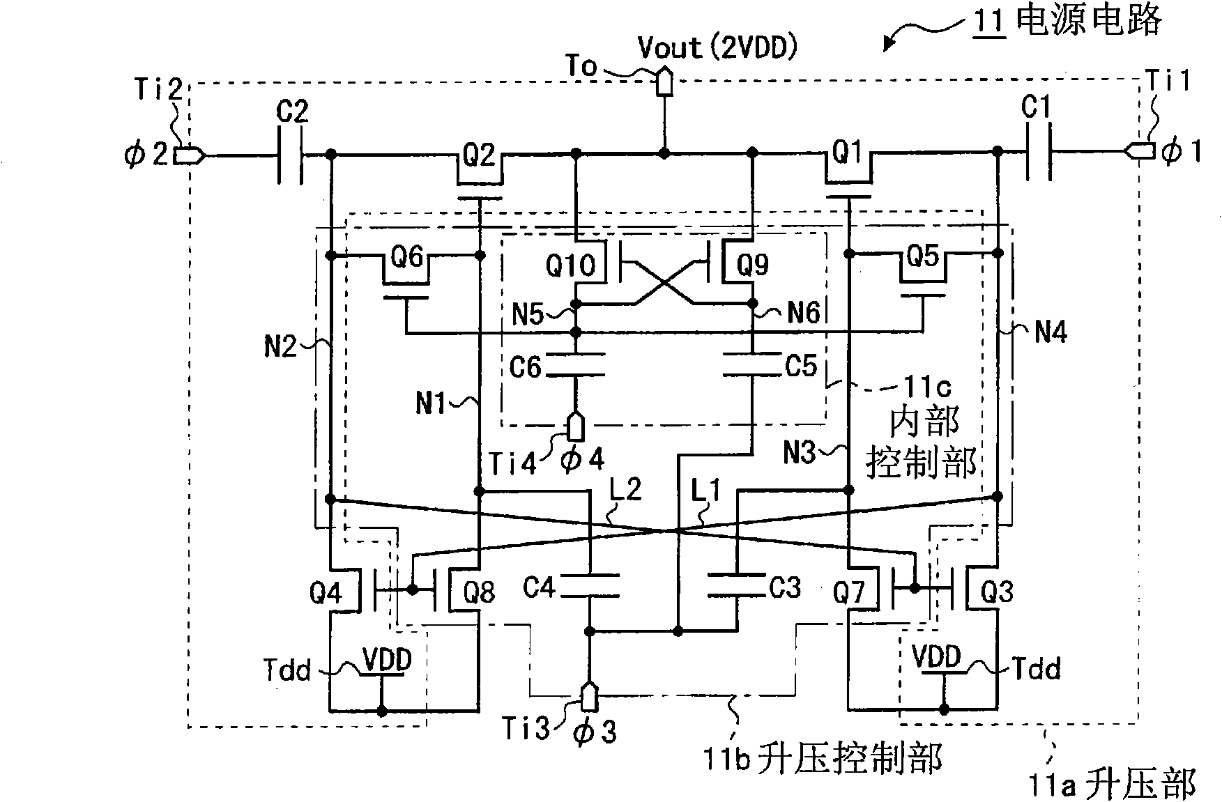
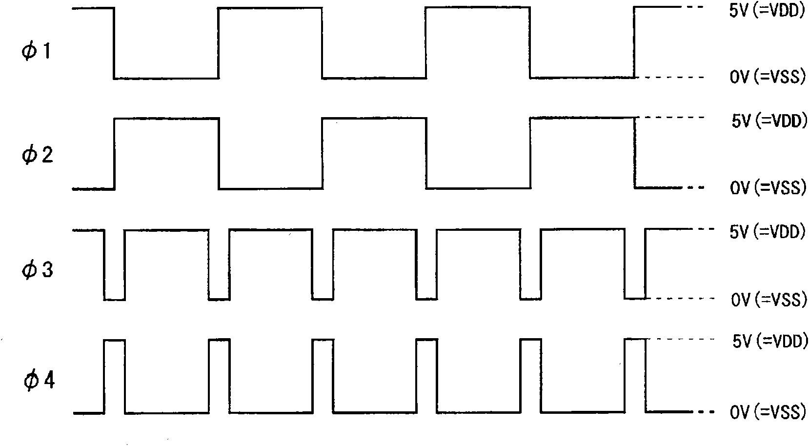
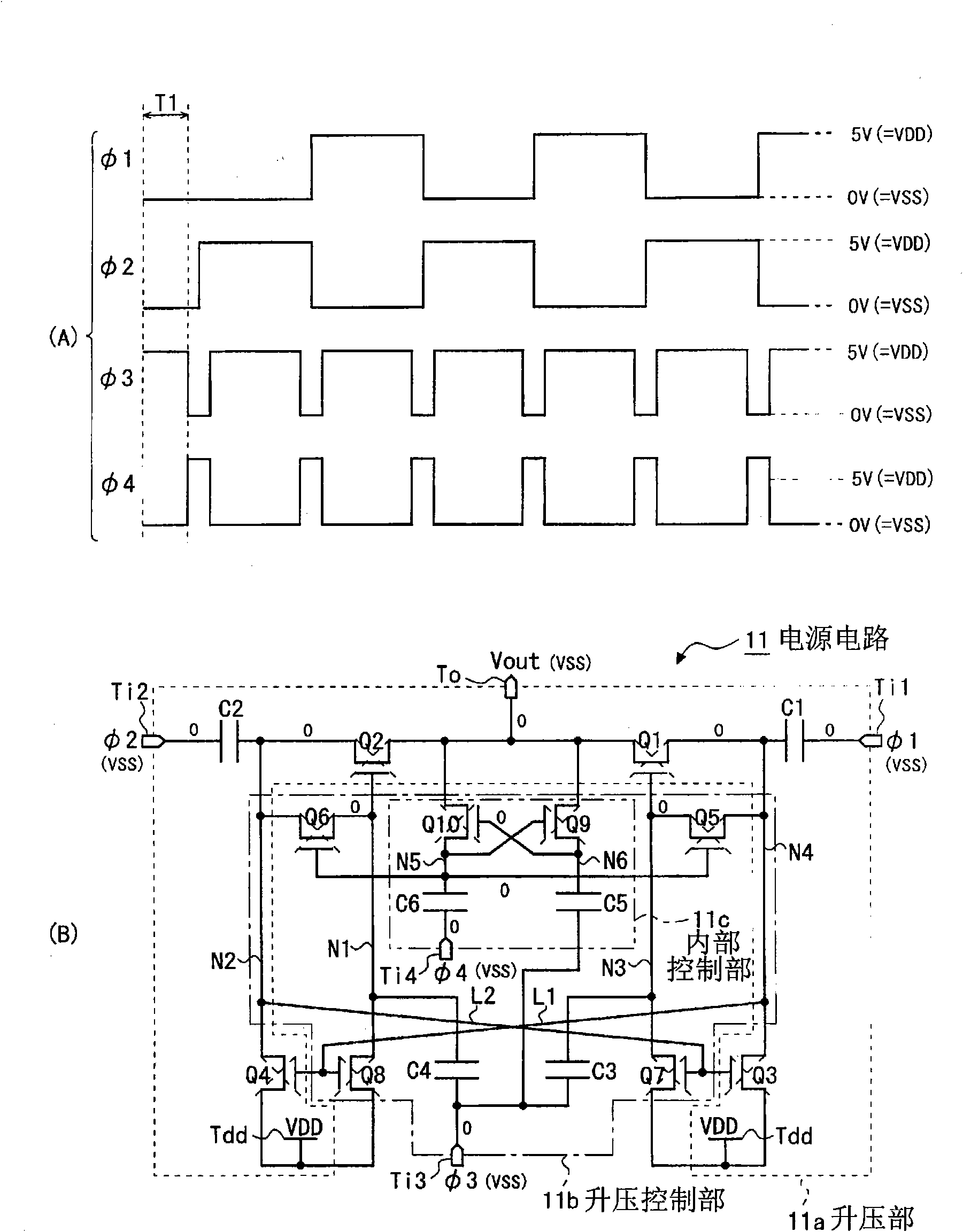
[0074] figure 1It is a circuit diagram showing the configuration of a power supply circuit according to an embodiment of the present invention. This power supply circuit 11 includes a booster section 11a that generates a boosted power supply voltage Vout (=2VDD) by complementary boosting of an input power supply voltage VDD (>0) applied from the outside, and a control booster voltage applied to the booster section 11a. The step-up control unit 11b for operating signals has external terminals for respectively receiving the first and second clock signals for driving the step-up unit 11a from the outside. The first and second input terminals Ti1, Ti2; used to receive the third clock signal used to boost the signal of the control booster 11a The third input terminal Ti3; for receiving the fourth clock signal for boosting the internal control signal of the bo...


PUM


Abstract

A power supply circuit including a charge pump boost section which does not cause threshold reduction even if only N-channel type transistors are used as switching elements. When a boosted voltage is obtained at one end (N4) of a first capacitor (C1) in a boost section (11a), a boost control section (11b) turns on a first transistor (Q1) by applying the boosted voltage to a third capacitor (C3) to further boost the voltage. When a boosted voltage is obtained at one end (N2) of a second capacitor (C2) in the boost section (11a), the boost control section turns on a second transistor (Q2) by applying the boosted voltage to a fourth capacitor (C4) to further boost the voltage. Thus, threshold reductions of the first and second transistors (Q1, Q2) as output-side switching elements are eliminated.

Description

technical field [0001] The present invention relates to a power supply circuit, and more specifically, to a power supply circuit including a booster for boosting a power supply voltage by a charge pump method, and a driver monolithic display device including such a power supply circuit. Background technique [0002] Conventionally, a DC-DC transformer that boosts a power supply voltage using an inductor is known. However, since an inductance element is required in such a DC-DC transformer, miniaturization is not easy, and it is difficult to realize it as a semiconductor circuit. Therefore, when boosting the power supply voltage of portable devices such as mobile phones or integrated circuits, a charge pump circuit composed of capacitors and switching elements is used (see, for example, Patent Document 1 (JP-A-10-285911)). [0003] For example, in a liquid crystal display device provided in a mobile phone or the like, a charge pump circuit is used to generate a driving volta...

Claims


Application Information

Patent Timeline
Patent Type & Authority Applications(China)
IPC IPC(8): H02M3/07
CPCH02M3/073H02M2003/077H02M3/077
Inventor 西修司辻野幸生村上祐一郎佐佐木宁业天诚二郎
Owner SHARP KK
Why Eureka
Try Eureka