Eureka AIR delivers breakthrough ideas for toughest innovation challenges, trusted by R&D personnel around the world.

Hydraulic classifier

A technology of hydraulic classifier and sorter, which is applied in the direction of solid separation, wet separation, chemical instruments and methods, etc., can solve the problems of single flow state, instability, and small effective separation area in the separation area, and achieve guaranteed Grading accuracy and the effect of ensuring stability

Inactive Publication Date: 2010-09-29
HENAN POLYTECHNIC UNIV
View PDF5 Cites 7 Cited by
  • Summary
  • Abstract
  • Description
  • Claims
  • Application Information

AI Technical Summary

Problems solved by technology

The traditional hydraulic classifier uses the top feeding of the cylindrical structure, and only the rising water flow is an adjustment parameter. The flow state in the sorting area is single and unstable, and the effective sorting area is small; the cross-flow hydraulic classifier is changed from the top feeding of the traditional hydraulic classifier. For unilateral feeding, the slurry crosses the sorting body to ensure the stability of the flow state. Although the sorting efficiency has been improved, it is easy to cause some tailings to directly follow the feeding direction and discharge the polluted concentrate directly with the overflow; The hydraulic flotation classifier improves the separation efficiency by introducing a bubble generator and a counterfeit medicine system, but when the same mineral is classified, the air bubbles will be attached to the coarse particles and fine particles at the same time, hindering the sinking of the coarse particles

Method used


Image

  • Hydraulic classifier
  • Hydraulic classifier
  • Hydraulic classifier

Examples


Embodiment Construction

[0022] The present invention will be further described below in conjunction with embodiment (accompanying drawing):

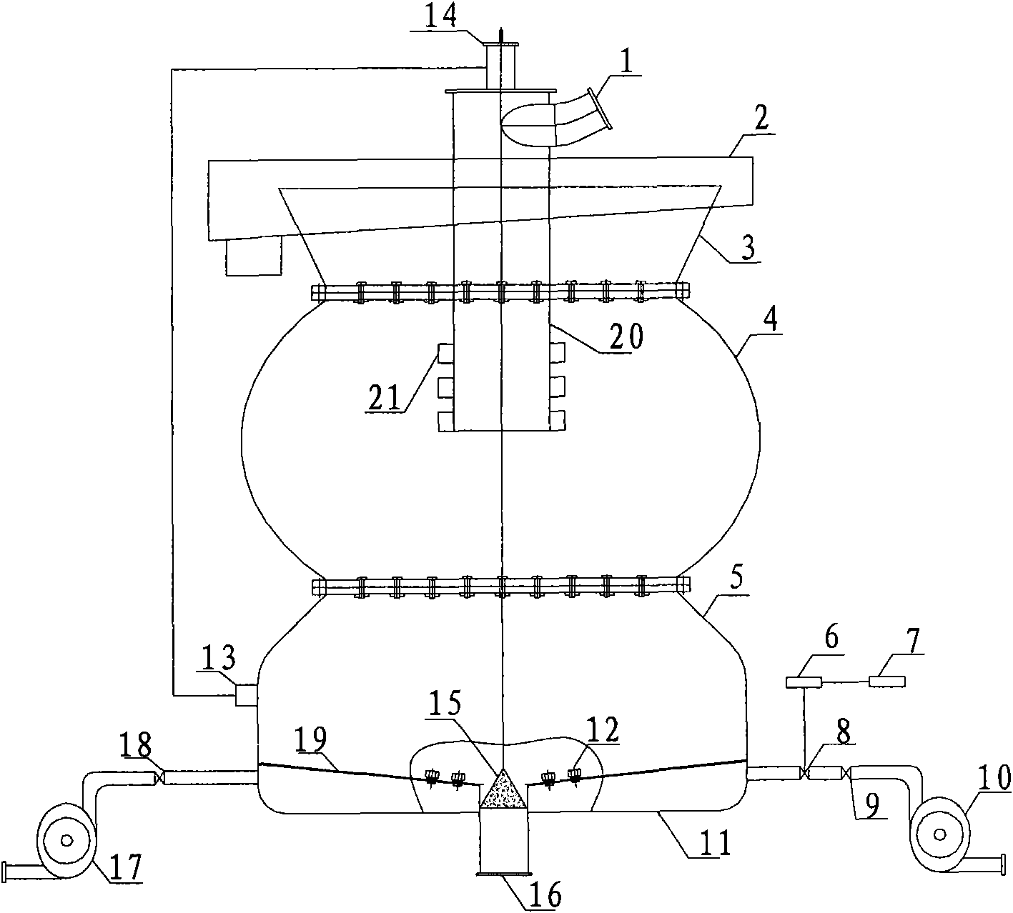
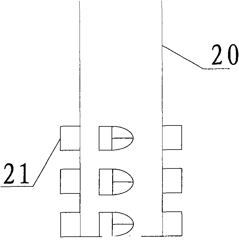
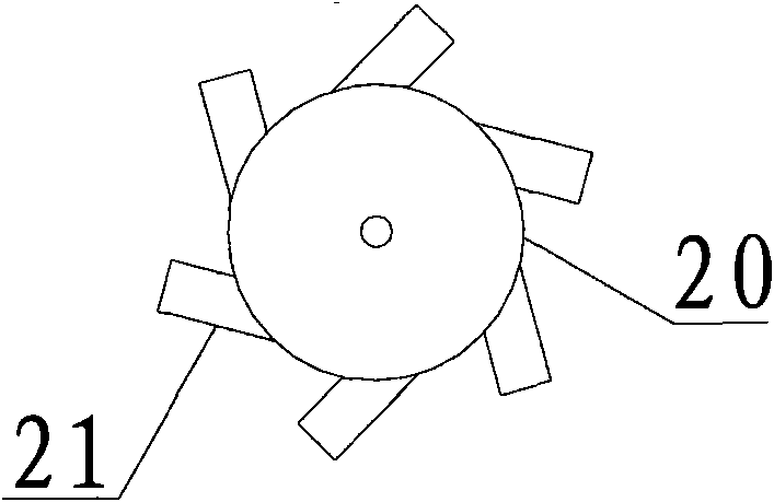
[0023] Such as figure 1 As shown, the hydraulic classifier of the present invention includes a classifier body with a card waist gourd-like structure consisting of an overflow collection section 3 at the top, a grading bed section 4 at the middle and an underflow collection section 5 at the bottom. And flange connection is adopted between each section, and the cross-sectional area of ​​the overflow collection section 3 is an inverted conical structure gradually increasing from bottom to top; The way of the axis is installed in the hollow cavity of the main body of the sorting machine through a fixed connector, and the lower end of the feeding well 20 extends vertically downwards to the middle part of the cavity of the grading bed section 4, and the upper section of the feeding well 20 is as high as At the upper edge of the overflow collection section 3; at the...


PUM


Abstract

The invention relates to a hydraulic classifier which is characterized by comprising a separator main body which is composed of an overflow collecting section positioned at the upper part, a classifying bed body section positioned at the middle part and an underflow collecting section positioned at the lower part and is of an anti-waist clamping calabash-shaped structure; a feeding well for adding materials is installed in the hollow cavity of the separator main body through a fixed connector in a mode of the feeding well and the separator main body having the same axial line, the lower end of the feeding well vertically extends downwards to the middle part of the cavity of the classifying bed body section, and the upper section of the feeding well is higher than the upper edge opening of the overflow collecting section; a water distributor is arranged at the lower part of the underflow collecting section, and the water distributor is composed of an inverted umbrella-shaped turbulent flow plate and a plurality of nozzles uniformly distributed on the turbulent flow plate; and an underflow pipe orifice and a float valve which downwards penetrate through the bottom of the underflow collecting section are arranged in the concave center position of the turbulent flow plate, and a water drum cavity formed by the space between the bottom surface of the turbulent flow plate and the bottom of the underflow collecting section is communicated with a water supply system through pipelines.

Description

technical field [0001] The invention relates to a fine-grained mineral grading equipment which can be used for grading or sorting operations of quartz sand and coarse coal slime, in particular to a hydraulic classifier. Background technique [0002] With the rapid development of the mining industry, scientific, harmonious and reasonable recycling of minerals to achieve energy saving and consumption reduction has become the current mainstream. Quartz sand is an important industrial mineral raw material. The particle size requirements are very strict in the production process. The performance of the grading process and supporting equipment directly determines the quality of the quartz sand product. It is very important to adopt a reasonable grading process and configure appropriate grading equipment to improve the quality of quartz sand. [0003] In the quartz sand production process, after the raw materials are crushed, washed, desilted and pulverized, they need to be classi...

Claims


Application Information

Patent Timeline
IPC IPC(8): B03B5/66B03B11/00
Inventor 焦红光惠兵吴彬姚军廖建国
Owner HENAN POLYTECHNIC UNIV
Why Eureka
Eureka Blog
Learn More