Eureka AIR delivers breakthrough ideas for toughest innovation challenges, trusted by R&D personnel around the world.

Constant pressure type hydraulic distance-regulating device

A distance adjustment device and hydraulic technology, which is applied in the field of distance adjustment devices, can solve the problems of display scale deviation, affecting work continuity, and large mechanical transmission inertia, so as to eliminate the influence of distance adjustment accuracy, ensure work continuity, and realize accurate The effect of control

Active Publication Date: 2010-09-29
大连橡胶塑料机械有限公司
View PDF2 Cites 2 Cited by
  • Summary
  • Abstract
  • Description
  • Claims
  • Application Information

AI Technical Summary

Problems solved by technology

[0005] 1. The large inertia of the mechanical transmission makes it difficult to accurately position the roller distance during the adjustment process
[0006] 2. Due to the difference in the output speed of the motor and the existence of mechanical transmission gaps, the synchronization of the roller spacing on both sides of the roller is poor during adjustment.
[0007] 3. Due to the large gap between the distance adjustment device and the safety device, which cannot be eliminated, there is an empty stroke of about 3mm during the distance adjustment process, and there is no display on the dial, so that the displayed scale is different from the actual roller distance. There is a large deviation
[0008] 4. The adjustable range of the distance adjustment speed is small, which does not meet the European CE safety standard, which affects the sales to users who implement the European CE standard.
[0009] 5. The protection pressure value of the safety plate of gray cast iron is a discrete value, usually the deviation range is about ±100kN, which cannot realize the precise protection of the equipment
[0010] 6. After the safety sheet is broken, the replacement time is longer and the work intensity is greater, which affects the continuity of work

Method used


Image

  • Constant pressure type hydraulic distance-regulating device
  • Constant pressure type hydraulic distance-regulating device
  • Constant pressure type hydraulic distance-regulating device

Examples


Embodiment Construction

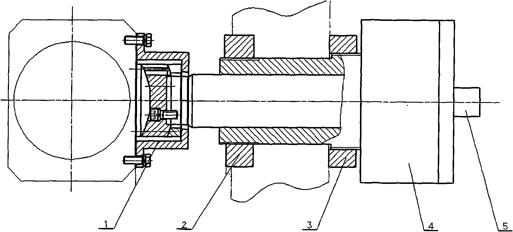
[0028] The specific implementation is as figure 1 Shown:

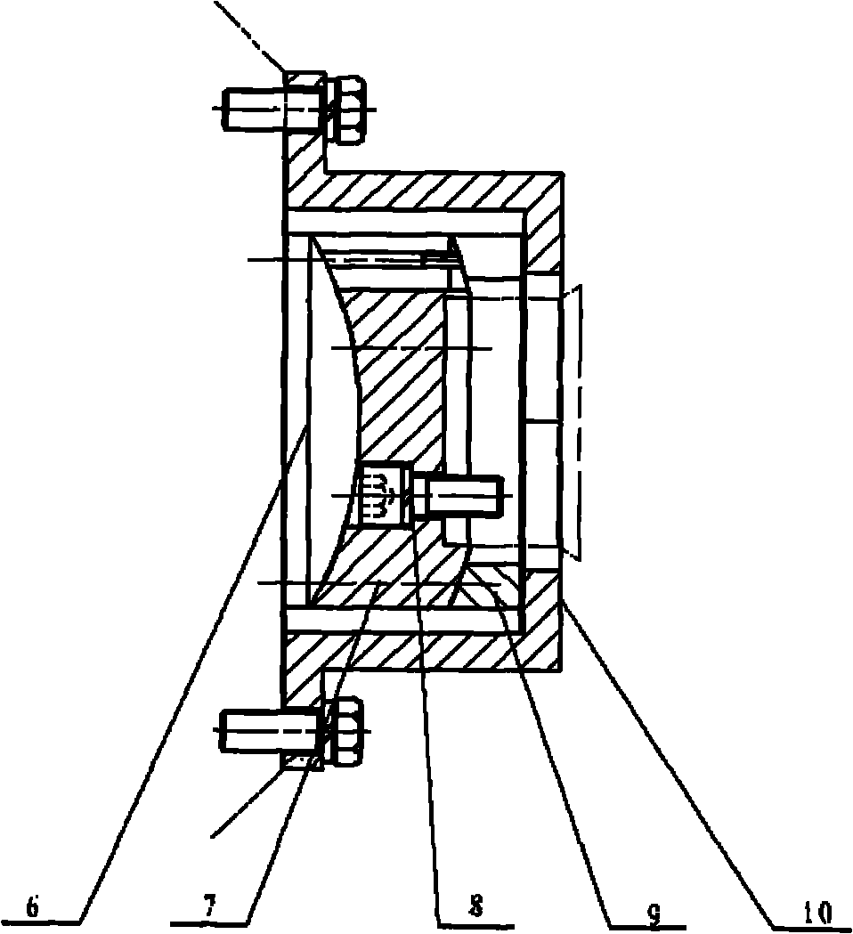
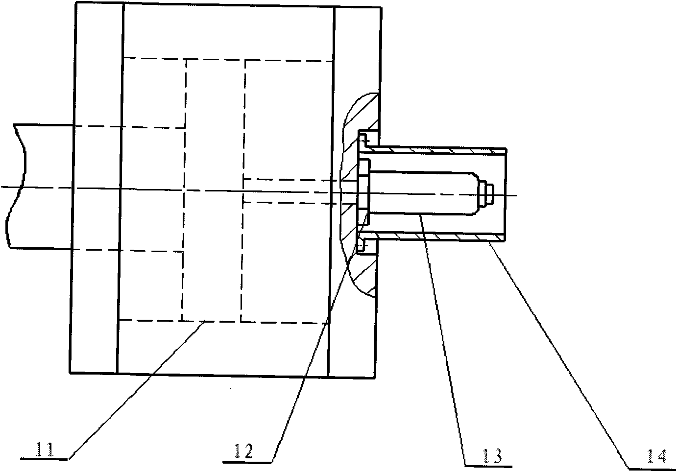
[0029] 1. Working process of voltage stabilization: After the low-pressure start of the oil pump, the oil pump supplies oil to the rodless cavity, and the roller moves quickly to the target roller distance δ. After a certain distance from the target roller distance δ, it changes to a slow forward movement and advances in parallel to δ- After 0.1mm, switch the solenoid valve to fill the rod cavity of the cylinder with oil and return the cylinder to the target roller pitch δ+0.1mm, then pressurize the two cylinders alternately to the rated pressure and maintain it, and then normal rubber mixing can be performed ; When the oil cylinder loses pressure during the working process, open the control valve for charging; when the roller is offset back and forth, repeat the above process to re-establish the pressure. The whole process is automatically completed by the signal feedback of displacement and pressure and the control prog...


PUM


Abstract

The invention provides a constant pressure type hydraulic distance-regulating device, relating to a distance-regulating device for regulating a roll gap of an open mill. The traditional distance-regulating device of an open mill is a mechanically combined structure of a motor, a decelerator, a worm wheel-worm, a lead screw-nut and the like, which has the defects of difficult accurate positioning, poor synchronization, about 3mm of idle stroke in a forward-backward conversion of a distance-regulating process, no display on a dial, incapability of accurately protecting a device because a protective pressure value of a safety sheet of a grey iron is a discrete value which always has a deviation area about + / -100kN and the like. The constant pressure type hydraulic distance-regulating device highly controls the accuracy of roll gap, effectively provides accuracy of safe protection pressure, improves the operational reliability of an open mill and satisfies the requirement of European certification safety standards.

Description

Technical field [0001] The invention relates to a pitch adjusting device for adjusting the size of a roll gap on an open mill, in particular to a constant pressure hydraulic pitch adjusting device. Background technique [0002] The open mill is one of the most commonly used basic equipment for product processing in the rubber and plastic industries. [0003] The distance adjustment device of the open mill is used to adjust the distance between the two rollers of the open mill, so that the open mill can work at different distances between the rollers, and together with the safety device, form the safety protection device of the open mill to prevent The roller, frame, bearing and other key components are damaged due to the overload of the roller. [0004] Because the original mill pitch adjusting device uses a mechanical combination structure such as a motor, a reducer, a worm gear-worm, a screw-nut, etc., the safety protection uses a gray cast iron safety sheet, which is common in th...

Claims


Application Information

Patent Timeline
IPC IPC(8): B29B7/72
Inventor 黄树林李元凯刘传亮盛凯
Owner 大连橡胶塑料机械有限公司
Why Eureka
Eureka Blog
Learn More