
Manufacturing method of thermal column

A technology of heat column and heat transfer element is applied in the field of structure and manufacture of heat transfer element of high-power LED light source to achieve the effect of small thermal resistance and ensure normal operation.

Active Publication Date: 2010-09-29
嘉善恒杰热管科技有限公司
View PDF4 Cites 6 Cited by
  • Summary
  • Abstract
  • Description
  • Claims
  • Application Information

AI Technical Summary

Problems solved by technology

[0003] The invention provides a method for making a heat column. The structure makes the part of the main body of the heat transfer element part that needs to be brazed between the bottom plate and the pipe body set up a cross-section that is rectangular, triangular, arc-shaped, and combinations thereof. Solder isolation measures, wherein the capillary structure in the cavity is sintered copper powder can also effectively ensure that the silver alloy solder passes through the material separation tank without being sucked into the capillary structure in the cavity, greatly improving the welding yield; Leakage problem caused by bad

Method used


Image

  • Manufacturing method of thermal column
  • Manufacturing method of thermal column
  • Manufacturing method of thermal column

Examples


Embodiment Construction

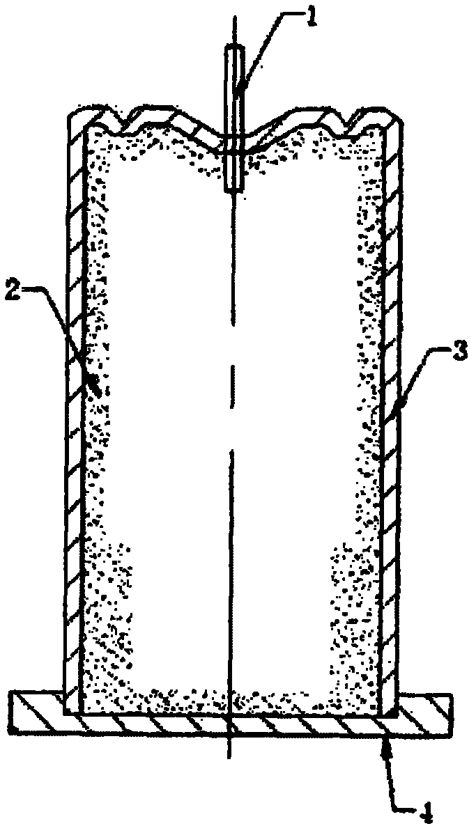
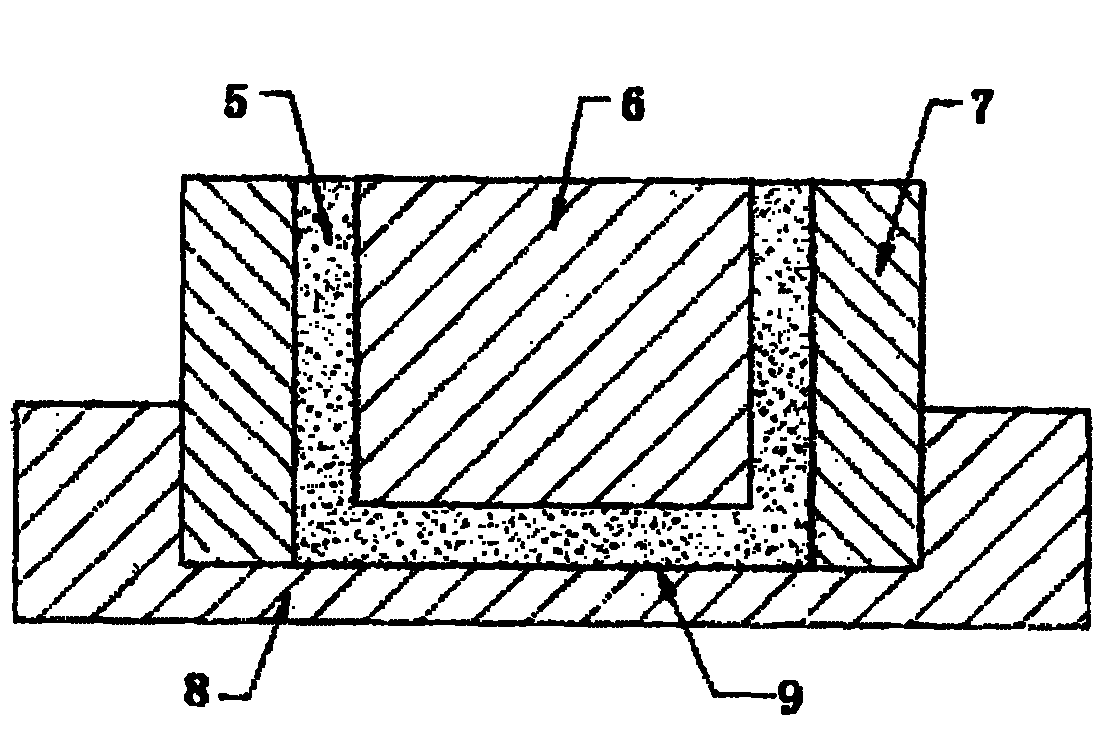
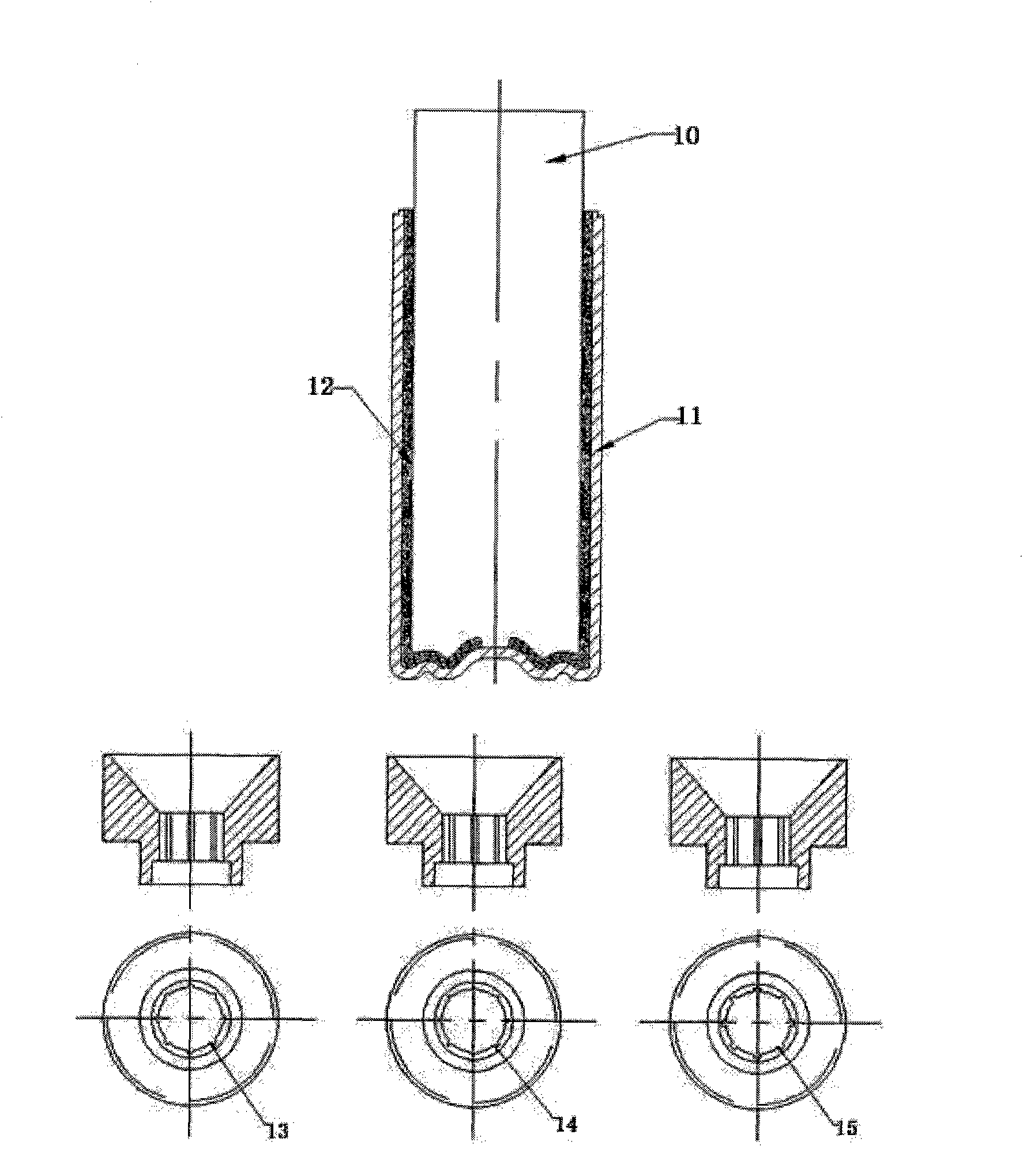
[0052] The method of assembling and welding hot column sintering is decomposed into sub-item sintering, assembly and then brazing. The thermal column body is put into the mandrel, and the electrolytic copper powder is vibrated into the interlayer through a special funnel for sintering. The evaporation section of the bottom plate is used The fixture is positioned and sintered to form a sintered copper powder layer that meets the required shape. The heat column body 2 is assembled with the base plate 1, so that the sintered layer on the base plate is embedded in the copper powder sintered layer of the tube body. The effect is that the sintered layers of each part of the heat column form a complete The connecting body is very conducive to the smooth circulation of the working fluid; a silver alloy welding wire ring is installed between the heat column tube body and the bottom plate, and a liquid injection and vacuuming small tube and a welding wire ring are placed in the φ2 hole in...


PUM

PropertyMeasurementUnit
Diameteraaaaaaaaaa
Diameter sizeaaaaaaaaaa
Wall thicknessaaaaaaaaaa

Abstract

The invention provides a structure of a heat transfer element, i.e. thermal column and a manufacturing method thereof. Stamping or extrusion is utilized to prepare pure copper metal barrel and a base plate; the inner cavity of the thermal column is provided with various capillary structures, such as sintered copper powder, copper nets, grooves and the like; after being sintered, the capillary structures are assembled to cause capillary tissues in the cavity to be fully communicated, and the thermal column is obtained by welding, injection and vacuum degassing. The invention can effectively solve the problem of working medium backflow and blockade in the processes of liquid heat transfer medium evaporation and condensation phase change so as to greatly improve heat transfer performance; asthe heat radiation core element, the thermal column can satisfy the operating requirements on high heat dissipation power and light weight of computer microprocessors, large-power LED illumination and integrated circuit radiators.

Description

technical field [0001] The invention relates to a core component of a heat dissipation device, in particular to a structure and a manufacturing method of a high-power LED light source heat transfer component used for heating electronic components. Background technique [0002] Most electronic products such as computers, communications, and photoelectric lighting will generate heat when they work. Solving the problem of heat dissipation plays a vital role in the normal operation and life of electronic products. Radiators made of heat columns as core heat transfer components have shown It is a heat dissipation component suitable for the development of new generation electronic products; it has achieved very good results in solving the heat dissipation of integrated single high-power LED lighting sources; in recent years, thermal column products have developed rapidly, but the structure is relatively single, very good There are many deficiencies in the solution to the complete ...

Claims


Application Information

Patent Timeline
IPC IPC(8): F28D15/04B23P15/26B22F7/04B22F5/00
CPCF28D15/046F28D15/0283
Inventor 杨互助苏维波杨子杰
Owner 嘉善恒杰热管科技有限公司
Learn More