Automatic electric connector assembling method and automatic electric connector assembler
An electrical connector and automatic assembly technology, which is applied in the field of automatic assembly machines, can solve the problems of low production efficiency, high production cost, and low degree of automation, and achieve the effects of improving productivity, flexible and convenient production and use, and high degree of automation
- Summary
- Abstract
- Description
- Claims
- Application Information
AI Technical Summary
Problems solved by technology
Method used
Image

Examples
Embodiment Construction
[0027] A preferred embodiment of the electrical connector automatic assembly method provided by the present invention is as follows:
[0028] A method for automatic assembly of electrical connectors, comprising steps in the following order:
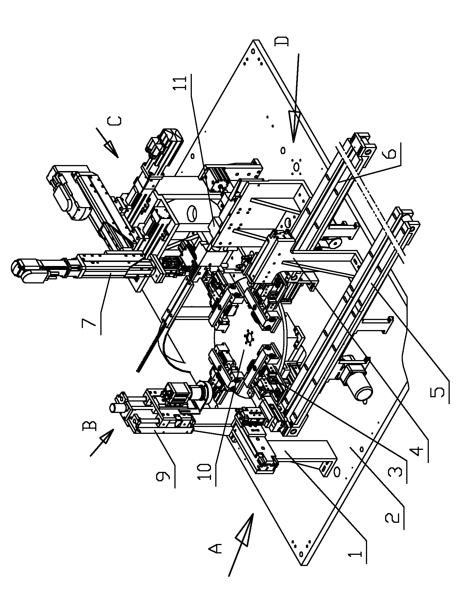
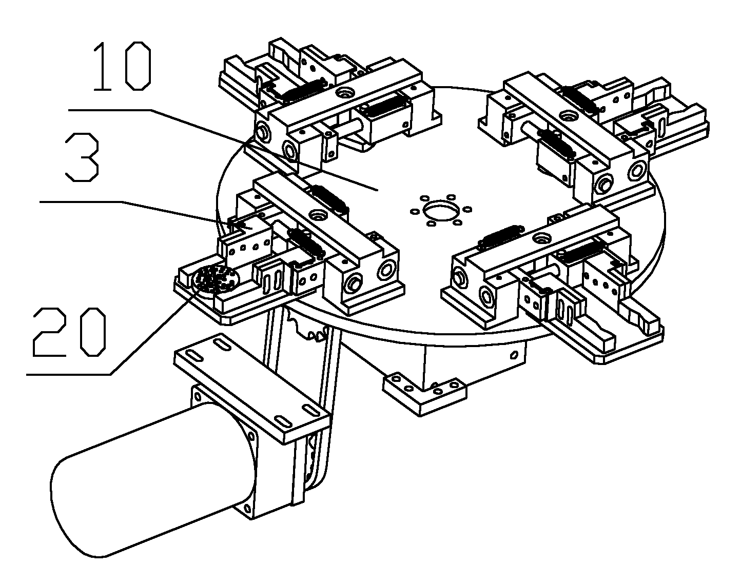
[0029] (1) An indexing turntable is set horizontally. Along the circumferential direction of the indexing turntable, there are loading stations, image detection stations, inserting stations and unloading stations in sequence. The indexing turntable corresponds to each station. The fixtures for clamping the parts with holes are arranged in turn, and the imaging device of the image detection system is correspondingly installed on the image detection station;
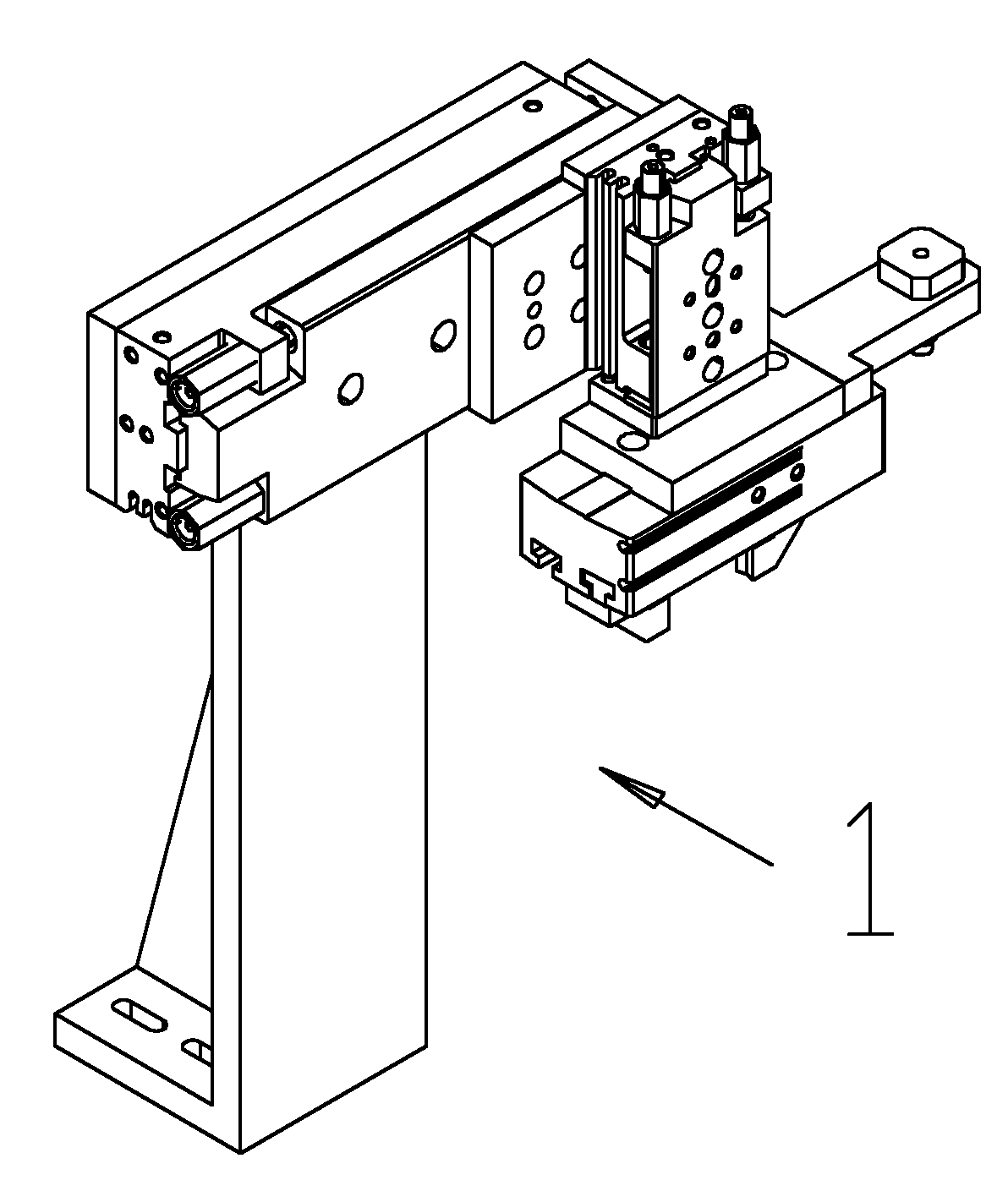
[0030] (2) Feeding: At the feeding station, the correspondingly set feeding manipulator grabs the parts with holes and moves them to the fixture on the indexing turntable at this station, and the parts with holes are clamped by the fixtures;
[0031] (3) Acquire image information and...
PUM
 Abstract
Description
Claims
Application Information