
Heat pump with heat recovery

A heat and liquid pump technology, used in cogeneration, fuel cell heat exchange, electrochemical generators, etc., can solve problems such as expensive heat sources

Inactive Publication Date: 2010-09-29
CARRIER CORP
View PDF0 Cites 30 Cited by
  • Summary
  • Abstract
  • Description
  • Claims
  • Application Information

AI Technical Summary

Problems solved by technology

In the case of hydronic / hot water heat, steam heat and hot water heaters, the heat source is usually natural gas, oil oil, etc., which have become relatively expensive in recent years

Method used


Image

  • Heat pump with heat recovery
  • Heat pump with heat recovery
  • Heat pump with heat recovery

Examples


Embodiment Construction

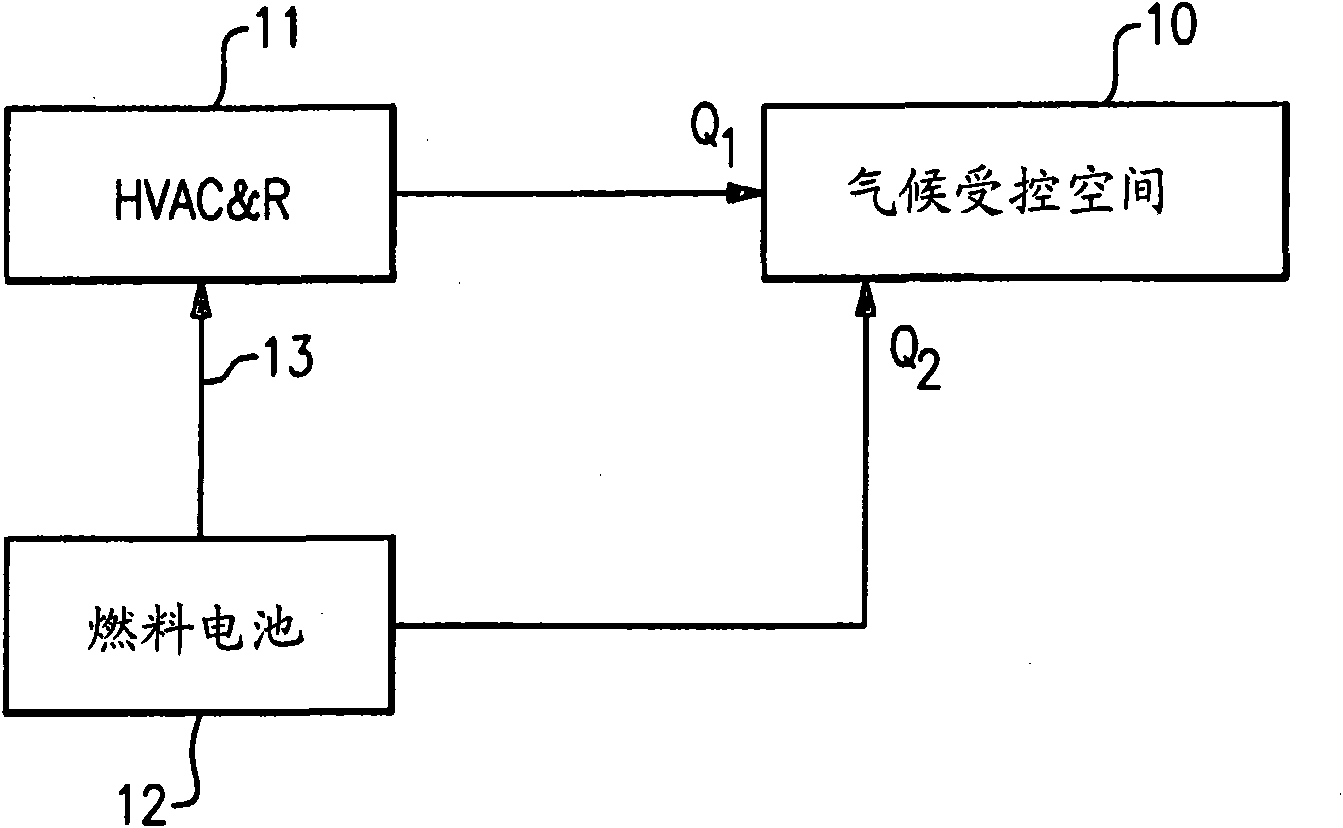
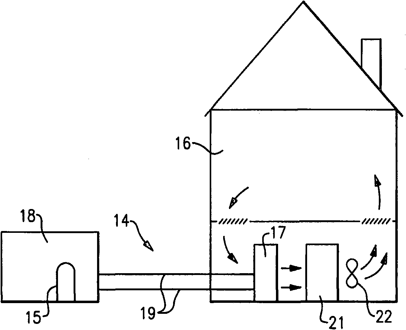
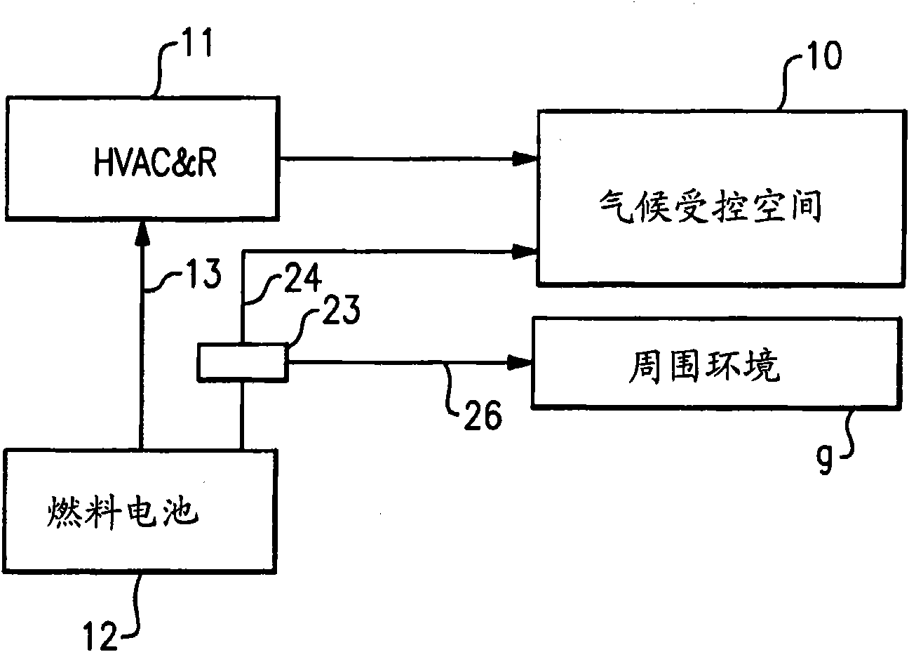
[0013] exist figure 1 A typical HVAC system 11 is schematically shown in , which may be installed to provide a comfortable environment in buildings such as commercial establishments, residences, hospitals, schools and the like. Such systems may include, but are not limited to, air conditioning and / or heat pumps, chilled water or salt water systems, and furnaces and / or hydronic heating systems, for example. A hot water heater is also available. Typically, the air conditioning system will operate in the summer, the furnace will operate in the winter, and the heat pump will operate in both seasons. The length of the cooling and heating seasons will depend on geographic location and specific applications.

[0014] A fuel cell 12 is provided for the purpose of delivering electrical energy via electrical lines 13 to the HVAC system. This arrangement allows the fuel cell 12 to provide all required electrical power to the HVAC system, and in this case, the primary power source. On...


PUM


Abstract

A fuel cell is provided to furnish electrical power to an HVAC&R system, and the waste heat from the fuel cell is transferred to a secondary fluid directed to flow to the climate-controlled space of a building during periods of time in which heating is required. The heat rejected by the fuel cell may be a supplemental or primary source of heat as well used for precise temperature control within the climate-controlled space of the building. A channeling assembly is used to selectively direct the fuel cell heat either to and / or away from the climate-controlled space served by the HVAC&R system. Higher energy efficiencies of the HVAC&R equipment are achieved, and the 'cold blow' phenomenon is reduced or eliminated.

Description

technical field [0001] The present invention relates generally to heat pumps and water heaters, and more particularly to the use of fuel cells for heat pumps and water heaters. Background technique [0002] Fuel cells are beginning to gain a foothold as a power source for heating, ventilation, air conditioning and refrigeration equipment (HVAC&R). Thus, fuel cells can be used as a primary power source, such as in isolated areas where electrical utilities cannot be reliably established, so that all electrical power for the HVAC&R system is provided solely by the fuel cells. Fuel cells can also be used as a supplementary power source in emergency situations, such as in the event of power outages or power failures due to weather conditions, etc., and where the grid is overloaded or existing conventional power sources are limited. [0003] Currently, fuel cells have an efficiency of about 40% to 50%, so that a large amount of heat is generated by the fuel cell during its operat...

Claims


Application Information

Patent Timeline
Patent Type & Authority Applications(China)
IPC IPC(8): H01M8/04
CPCY02B90/16H01M2250/405H01M8/04007Y02E60/50Y02B90/10
Inventor A·利夫森M·F·塔拉斯
Owner CARRIER CORP
Learn More