
Robot joint redundancy control system and control method thereof

A technology of robot joints and redundant control, applied in the field of servo control systems, can solve the problem of inability to reconfigure the resources of the primary system and backup system, and achieve the effect of ensuring normal operation.

Inactive Publication Date: 2010-10-06
HARBIN INST OF TECH
View PDF5 Cites 4 Cited by
  • Summary
  • Abstract
  • Description
  • Claims
  • Application Information

AI Technical Summary

Problems solved by technology

[0005] In order to solve the defect that the existing cold backup robot joint control system cannot realize the resource reconfiguration of the primary system and the backup system, the present invention provides a robot joint redundant control system and control method

Method used


Image

  • Robot joint redundancy control system and control method thereof
  • Robot joint redundancy control system and control method thereof
  • Robot joint redundancy control system and control method thereof

Examples


specific Embodiment approach 1

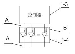
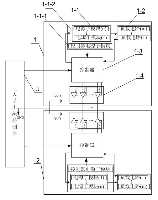
[0018] Specific implementation mode one: according to the instructions attached figure 1 , 2 and 3 specifically illustrate this embodiment, a robot joint redundant control system described in this embodiment, which includes a master control unit 1 and a backup control unit 2, and the master control unit 1 and the backup control unit 2 have the same structure , the ground wire of the primary control unit 1 and the ground wire of the backup control unit 2 are both connected to the control system return line, and the primary control unit 1 and the backup control unit 2 are connected through a signal line,

[0019] The primary control unit 1 includes a power supply module 1-1, a load circuit group 1-2, a controller 1-3 and an information exchange control module 1-4,

[0020] The power module 1-1 is used to provide power to the controller 1-3, and is also used to turn on or turn off the power output to the load circuit group 1-2 after receiving the power control signal from the co...

specific Embodiment approach 2

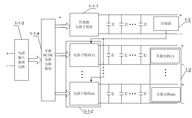
[0024] Embodiment 2: This embodiment is a further description of Embodiment 1. The power supply module 1-1 in Embodiment 1 includes a controller power supply submodule 1-1-1 and a load circuit power supply submodule group 1- 1-2,

[0025] The controller power supply sub-module 1-1-1 is used to provide power to the controller 1-3,

[0026] The load circuit power supply submodule group 1-1-2 includes n power supply submodules, n>1, and is a natural number, and the load circuit group 1-2 includes m load circuits, m>1, and is a natural number, The load circuit power supply submodule group 1-1-2 is used to turn on or turn off the power output to the load circuit group 1-2 after receiving the power control signal from the controller 1-3, so as to realize the control of the load circuit Individual control of each load circuit in groups 1-2.

specific Embodiment approach 3

[0027] Embodiment 3: This embodiment is a further description of Embodiment 1 or 2. The information exchange control modules 1-4 described in Embodiment 1 or 2 are multiple tri-state bidirectional data buffers.


PUM


Abstract

The invention discloses a robot joint redundancy control system and a control method thereof, which relate to the field of servo control systems and solve the defects that a traditional cold backup robot joint control system cannot re-configure the resources of a master system and a backup system. The robot joint redundancy control system comprises a master control unit and a backup control unit, the master control unit and the backup control unit are in the same structure, the master control unit comprises a power supply module, a load circuit group, a controller and an information exchange control module, and the master control unit and the backup control unit are connected by a signal line; and the robot joint redundancy control method is realized based on the control system. The invention lays foundation for further improving the reliability of the joint control system.

Description

technical field [0001] The invention relates to the field of servo control systems, in particular to a robot joint redundancy control system and a control method. Background technique [0002] With the increase of my country's investment in space exploration, more and more electromechanical equipment will be put into space operation, and space robot, as a typical representative, has become a hot research field. Due to the loss of the protection of the earth's atmosphere in space, electromechanical equipment such as space robots must face drastic high and low temperature changes and strong space radiation. In addition, mechanical and electrical equipment such as space robots have weaknesses that cannot be repaired or the repair cost is too high. Special attention must be paid to improving system reliability and fault tolerance during the design process. [0003] At present, the joint control system of space robots generally improves the reliability of the system through redu...

Claims


Application Information

Patent Timeline
Patent Type & Authority Applications(China)
IPC IPC(8): B25J13/00
Inventor 郭闯强倪风雷刘宏介党阳
Owner HARBIN INST OF TECH
Learn More