
Method for cutting workpiece and device for changing rolling width of wire cutting workpiece

A technology for wire coils and workpieces, which is applied to fine working devices, working accessories, and knives of sawing machine devices, which can solve problems such as retention and achieve the effect of preventing wire jumping

Inactive Publication Date: 2010-10-06
KOMATSU NTC LTD
View PDF7 Cites 20 Cited by
  • Summary
  • Abstract
  • Description
  • Claims
  • Application Information

AI Technical Summary

Problems solved by technology

However, the purpose of this technology is not to prevent the separation or scattering of end materials, thereby maintaining the function of the wire saw and preventing danger.
Therefore, even if the technique of Patent Document 1 is simply used, the above-mentioned problems cannot be solved.

Method used


Image

  • Method for cutting workpiece and device for changing rolling width of wire cutting workpiece
  • Method for cutting workpiece and device for changing rolling width of wire cutting workpiece
  • Method for cutting workpiece and device for changing rolling width of wire cutting workpiece

Examples


Embodiment Construction

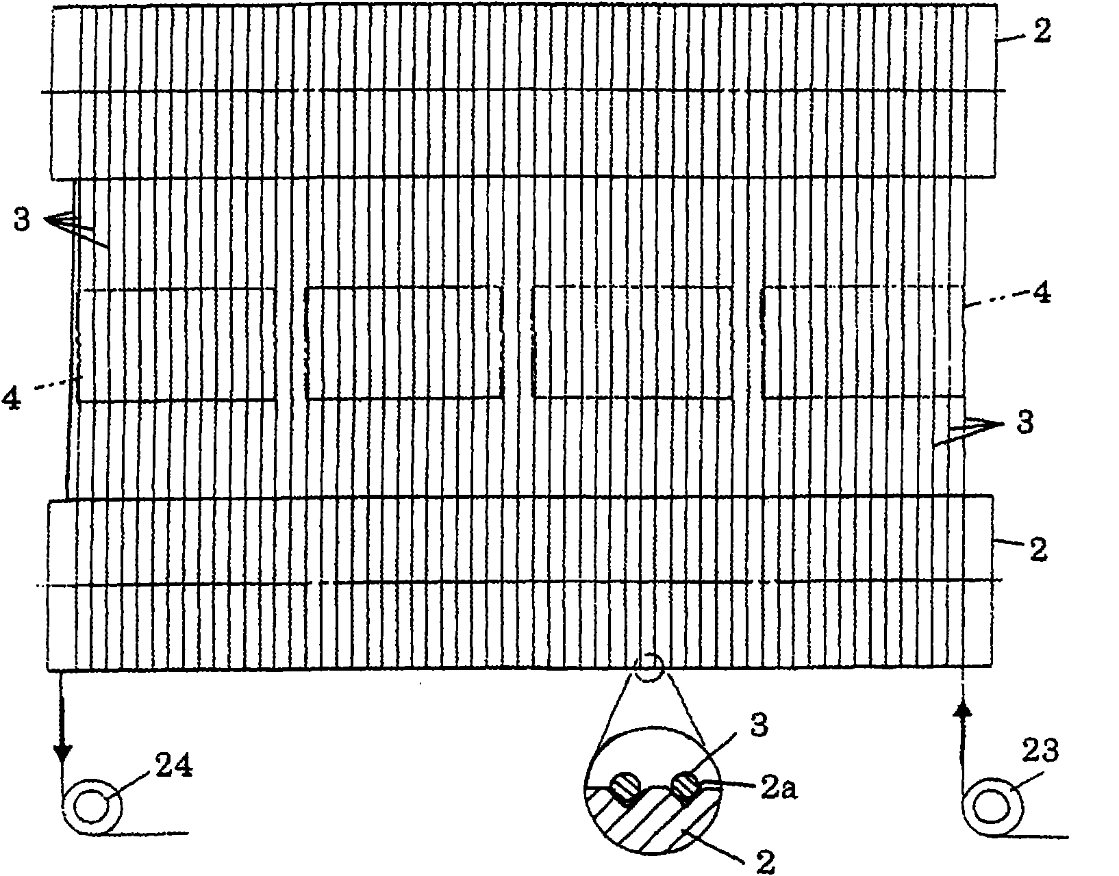
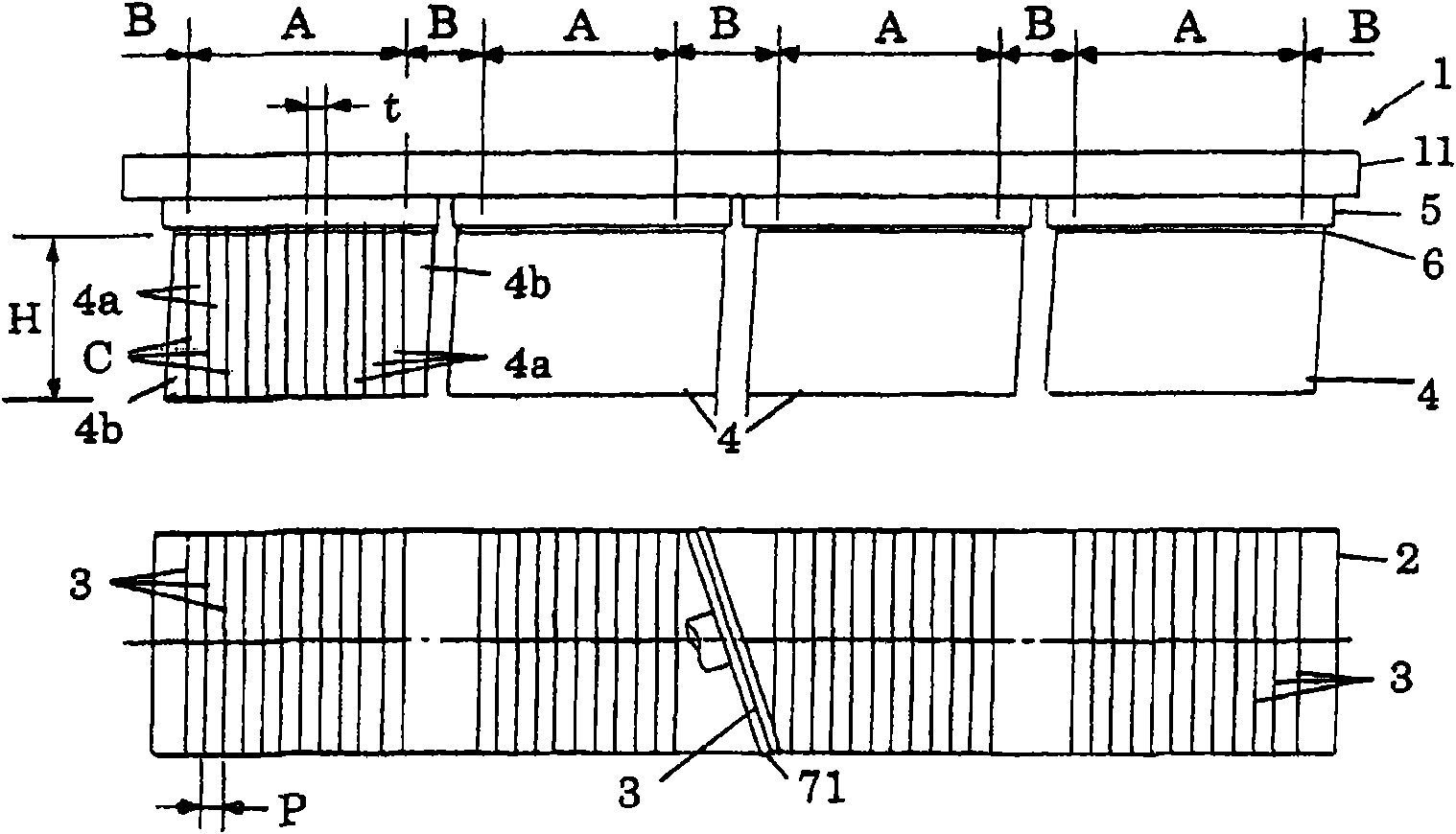
[0048] image 3 and Figure 4 It shows a method when a plurality of, for example, four workpieces 4 are simultaneously cut using the workpiece cutting method according to the present invention. At that image 3 as well as Figure 4 In, as an example of the wire saw 1, the multi-wound wire 3 is moved between two parallel main rollers 2, and four workpieces 4 are abutted on the wire 3 in the running state, thereby the workpiece 4 Cut to the target thickness t.

[0049] The wire 3 is pulled out by a delivery device not shown, and is wound in multiple times along the grooves 2a of the main rollers 2 between the plurality of main rollers 2 via the guide roller 23 with grooves, and is wound with the workpiece After forming parallel cutting areas at the positions facing each other, it is sent out to a winding device not shown via a guide roller 24 with grooves.

[0050] The grooves 2a of the main roller 2, such as Figure 4 As shown in the enlarged cross-sectional view in the circle, V-s...


PUM


Abstract

The invention provides a wire saw. Even the workpiece is cut off, the workpiece is constrained by an adhesive layer, the end material and the wire material are not interfered and the end material is prevented from entering into a groove of a main roller. Coiled wire materials travel between a plurality of parallel main rollers. The workpiece which is constrained on a rack by the adhesive layer is pressed on the wire material in a traveling state, the thickness of the workpiece cut to the target is t, and in the direction of target thickness t of the workpiece, two end portions of the workpiece have partially residual adhesive layer; and a workpiece cut-off area A is set in a range capable of ensuring necessary sizes (cut-off height H, cut-off length L and cut-off width W) of the workpiece; in the workpiece cut-off area A, the distance P between wire materials is set to a value corresponding to the target thickness t; and a wire material jump area B is set out of the workpiece cut-off area A; and there is no wire material in the range of the wire material jump area B, where the wire material is in interference with the workpiece.

Description

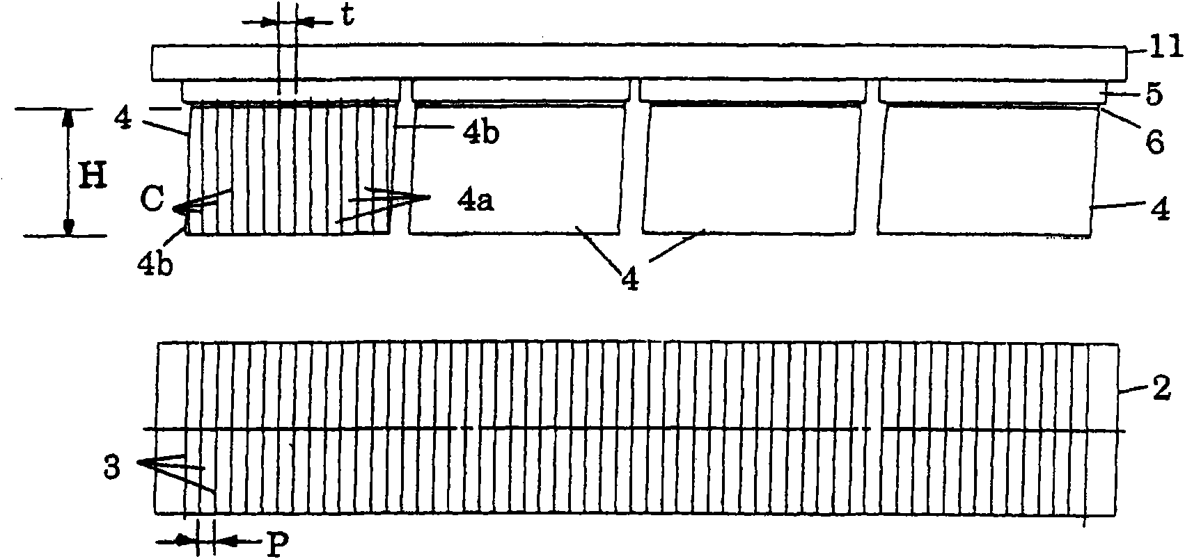
Technical field [0001] The present invention relates to a method for cutting a workpiece with a wire saw, and a device for changing the winding state of the wire during the cutting of the workpiece, particularly a part of the pitch, that is, the width of the wire winding corresponding to the shape of the workpiece. Background technique [0002] As a wire saw, a wire rod is repeatedly wound between main rolls, and the wire rod in a traveling state is pressed against a workpiece such as a silicon ingot to cut the workpiece into a product of a predetermined thickness. In this cutting process, in order to improve work efficiency, it is preferable that a plurality of workpieces are simultaneously cut. [0003] figure 1 and figure 2 It shows a general method when cutting a plurality of, for example, four workpieces 4 at the same time in a conventional wire saw. Each work 4 is held on a holder 5 made of glass by the bonding layer 6 on the upper surface. These workpieces 4 are bonded to...

Claims


Application Information

Patent Timeline
Patent Type & Authority Applications(China)
IPC IPC(8): B28D5/04B23D61/18
CPCB23D61/185B23Q17/20B26D1/547B28D7/04
Inventor 伊东靖弘小林茂雄阿部克彦长谷川洋介
Owner KOMATSU NTC LTD
Learn More