Method for preparing double-exchange biasing field type spin valve

A technology of bias field and spin valve, which is applied in the manufacture/processing of electromagnetic devices, static memory, instruments, etc., can solve the problems of complicated process, high cost, and degraded giant magnetoresistance performance, so as to simplify the preparation steps and increase the The effect of flexibility

Inactive Publication Date: 2010-10-06
UNIV OF ELECTRONICS SCI & TECH OF CHINA
View PDF3 Cites 6 Cited by
  • Summary
  • Abstract
  • Description
  • Claims
  • Application Information

AI Technical Summary

Problems solved by technology

[0006] Although the double-exchange bias field type spin valve can be easily obtained by using the deposition method under an external magnetic field to obtain double-exchange bias fields Hex1 and Hex2 in opposite directions, the process is relatively complicated and the cost is high, and the field size of Hex1 and Hex2 The setting of the ferromagnetic layer can only be realized by controlling the thickness of the ferromagnetic layer F1 and the ferromagnetic layer F2, which greatly limits the flexibility of the application of the double exchange bias field spin valve.
When annealing under an external magnetic field is used to prepare a double exchange bias field type spin valve, although a large exchange bias field can be obtained, due to the influence of temperature during high temperature annealing, interdiffusion between spin valve multilayer films will occur. Seriously, and degrade its giant magnetoresistance performance

Method used


Image

  • Method for preparing double-exchange biasing field type spin valve
  • Method for preparing double-exchange biasing field type spin valve
  • Method for preparing double-exchange biasing field type spin valve

Examples


Embodiment Construction

[0026] A method for preparing a double exchange bias field type spin valve includes the following steps:

[0027] Step 1: Using a thin film deposition process and under the action of an external magnetic field, a double exchange bias field type spin valve is prepared.

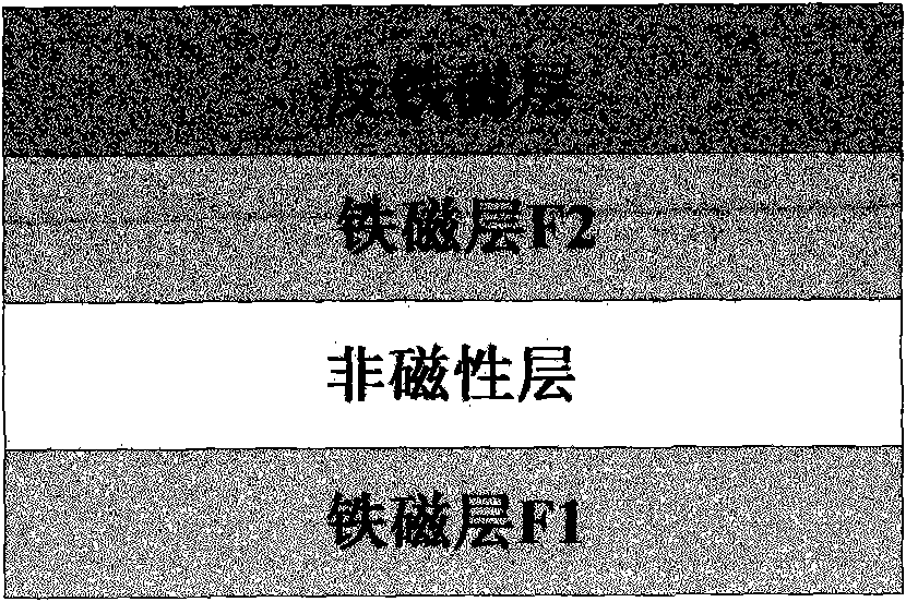
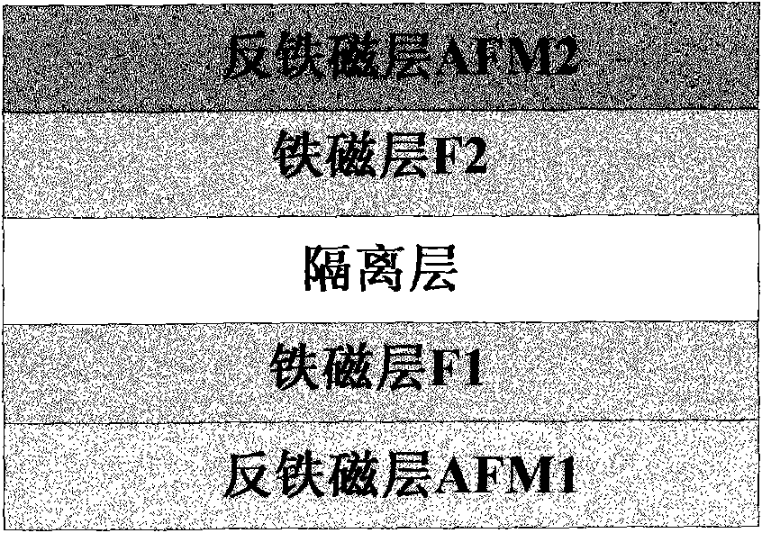
[0028] The structure of the double exchange bias field type spin valve is as figure 2 As shown, from the top of the substrate, there are buffer layer, antiferromagnetic layer AFM1, ferromagnetic layer F1, isolation layer, ferromagnetic layer F2, antiferromagnetic layer AFM2 and cover layer in order. The substrate can be Si substrate or glass substrate, the buffer layer material is Ta, the antiferromagnetic layer AFM1 and the antiferromagnetic layer AFM2 material are FeMn, NiMn, IrMn, PtMn or NiO, the ferromagnetic layer F1 and the ferromagnetic layer F2 The material is Ni, Fe, Co or Ni / Fe / Co alloy, the material of the isolation layer is Cu, and the material of the cover layer is Ta.

[0029] The external magnetic fi...


PUM


Abstract

The invention discloses a method for preparing a double-exchange biasing field type spin valve and belongs to the technical field of magnetic materials and components. The method comprises the steps of: preparing the double-exchange biasing field type spin valve by adopting the thin film deposition technology under the action of an external magnetic field, wherein the sizes of the exchange biasing fields are different, and the directions are the same; measuring the sizes of two exchange biasing fields through a vibrating sample magnetometer; and finally, applying external magnetic fields with the same size and opposite directions between the two exchange biasing fields, and applying pulse current on a ferromagnetic layer film surface having a lower exchange biasing field along the direction of the exchange biasing field simultaneously. The size and direction of the lower exchange biasing field can be changed according to the difference between the applied external magnetic fields H and the size of the pulse current. Therefore, different double-exchange biasing field type spin valves are obtained. By using the spin transfer effect to modulate the size and direction of the lower exchange biasing field in the double-exchange biasing field type spin valve, the preparation steps are simplified and the application flexibility of the double-exchange biasing field type spin valve is improved.

Description

Technical field [0001] The invention belongs to the technical field of magnetic materials and components, and relates to magnetic recording technology, in particular to a method for preparing a double exchange bias field type spin valve. Background technique [0002] The giant magnetoresistance (GMR) effect refers to the resistance change caused by an external magnetic field in the magnetic multilayer film material, and it has a wide range of application backgrounds in sensors and magnetic random access memories. The spin valve is currently the most important structure to realize the giant magnetoresistance effect. Due to its low saturation field and high sensitivity, the sensor and ultra-high-density storage technology based on the giant magnetoresistance effect have been developed by leaps and bounds. [0003] The basic structure of the spin valve is: free layer (ferromagnetic layer F1) / isolation layer (non-magnetic layer) / pinned layer (ferromagnetic layer F2) / bias layer (antifer...

Claims


Application Information

Patent Timeline
Patent Type & Authority Applications(China)
IPC IPC(8): H01L43/12G11C11/16
CPCG11C11/161
Inventor 唐晓莉张怀武荆玉兰苏桦钟智勇
Owner UNIV OF ELECTRONICS SCI & TECH OF CHINA
Why Eureka
Try Eureka