
Spray nozzle structure capable of regulating diameter of fogdrops rotationally along circumferential direction

A technology of rotating adjustment and spray head, applied in the direction of spraying device, spraying device, spraying device with movable outlet, etc., can solve the limitation of the ability and efficiency of absorbing the heat of high temperature flue gas, the lack of adjustable mechanism and strain capacity of the device, the flue gas Temperature changes and other problems, to achieve the effect of improving the atomization effect, the adjustment effect is obvious, and the speed of adjustment is improved

Inactive Publication Date: 2010-10-13
SHANGHAI UNIV OF ENG SCI
View PDF4 Cites 11 Cited by
  • Summary
  • Abstract
  • Description
  • Claims
  • Application Information

AI Technical Summary

Problems solved by technology

Analyzing each triangular "shower head" structure in the prior art, the cooling water enters the "shower head" from the upper pipeline, and then flows out from the simple round hole of the "shower head". Changes, and the device lacks adjustable mechanism and strain capacity, so the ability and efficiency of absorbing high-temperature flue gas heat are limited

Method used

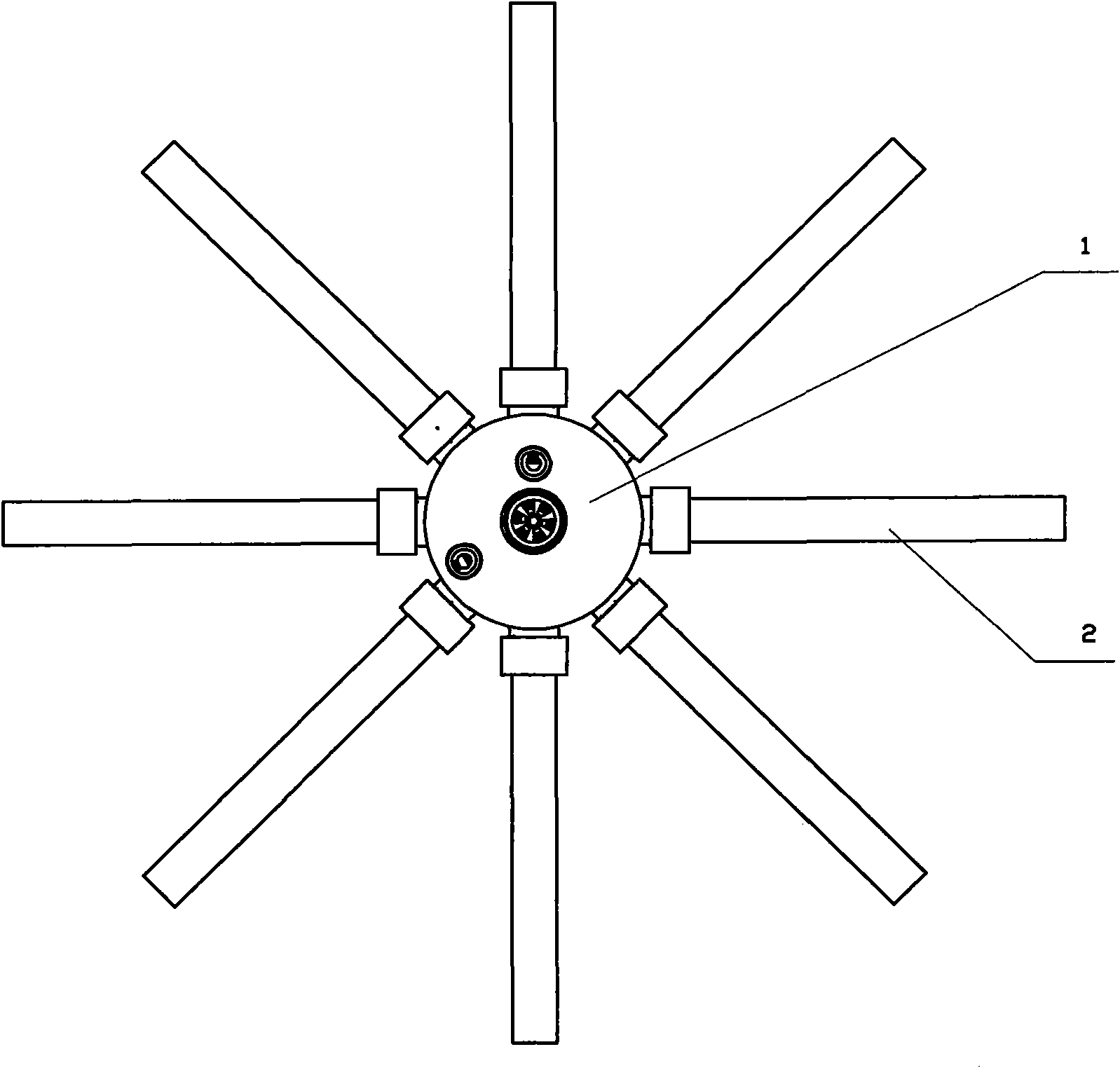

Image

  • Spray nozzle structure capable of regulating diameter of fogdrops rotationally along circumferential direction
  • Spray nozzle structure capable of regulating diameter of fogdrops rotationally along circumferential direction
  • Spray nozzle structure capable of regulating diameter of fogdrops rotationally along circumferential direction

Examples


Embodiment Construction

[0040] The structure of the present invention will be further described in detail below in conjunction with the accompanying drawings.

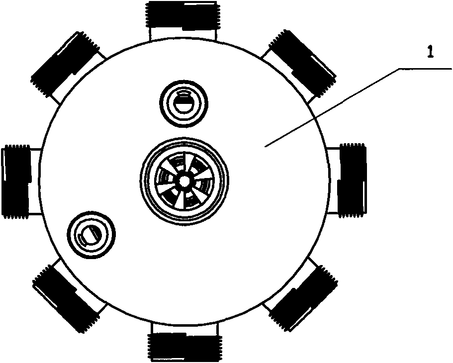
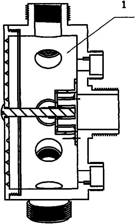
[0041]A cylindrical nozzle structure that rotates in the circumferential direction to adjust the diameter of the droplets. On the cylindrical wall of the cylindrical nozzle 1, a number of threaded horizontal water outlets are opened, respectively connected to a number of horizontal water spray pipes 2, and a circumferential rotation in the center Adjust the spray head structure of the droplet diameter, on the lower bottom plate 3 of the cylindrical spray head, on the circumference of different diameters from the inside to the outside, a plurality of water spray holes 3a are evenly opened; corresponding to the multiple water spray holes 3a opened on the circumference of different diameters , in the middle of the cylindrical shower head, a multi-circle water spray hole cover is set, that is, a multi-circle rotating ring piece 4 corresponding to ...


PUM


Abstract

The invention relates to the structure of a part of a device for heating water by using industrial high-temperature smoke, in particular to a spray nozzle structure capable of regulating the diameter of fogdrops rotationally along a circumferential direction, which is characterized in that: a plurality of water spray holes (3a) are reserved uniformly in circles with different diameters from the inside to the outside on a lower bottom plate (3) of a cylindrical spray nozzle; corresponding to the plurality of water spray holes (3a) reserved on in the circles with different diameters, a plurality of circles of water spray hole covers, namely a plurality of circles of rotary ring plates (4), are arranged in the middle of the cylindrical spray nozzle, and the lower edges of the rotary ring plates (4) are provided with raised water spray hole covers (4a) corresponding to the water spray holes (3a); and the upper edges of the rotary ring plates (4) all are provided with an arc external tooth section (4b) or arc internal tooth section (4b), a rotary handle (5) is arranged on the upper panel of the cylindrical spray nozzle (1), and tooth rings (5b) are arranged in a circumferential direction on the surface of the rotary shaft (5a) of a rotary handle (5) to be meshed with the arc external tooth section (4b) or arc internal tooth section (4b). In the technical scheme, the flow of sprayed water is controlled, and the atomization effect of the sprayed water drops is improved; and the water spray holes distributed in the plurality of circles can be regulated at the same time, and the mechanism is simple, reliable and stable.

Description

technical field [0001] The invention relates to the field of industrial flue gas waste heat utilization, in particular to a component structure of a water heating device using high-temperature flue gas discharged from industrial furnaces. Background technique [0002] In the energy saving and emission reduction tasks of industrial and civil buildings, the effective and active use of waste heat and waste heat is always a content that deserves great attention and has potential to be tapped. For example, about 15-25% of the heat energy of the fuel burned by a general gas-fired boiler is discharged into the atmosphere through the flue gas. The heat energy loss of the exhaust gas can be reduced by about 5-8%, but the exhaust gas temperature is still above about 150°C. Relative to the atmospheric temperature, the unused waste heat of this part of the flue gas still accounts for more than 10% of the incoming fuel heat. Where technical and economic conditions permit, recycling sho...

Claims


Application Information

Patent Timeline
Patent Type & Authority Applications(China)
IPC IPC(8): B05B1/18B05B1/30B05B3/02F28F25/06
Inventor 姜小敏陈闵叶孙培雷项阳李智忠
Owner SHANGHAI UNIV OF ENG SCI
Learn More