Supercharge Your Innovation With Domain-Expert AI Agents!

Gear pump

一种齿轮泵、齿轮花的技术,应用在泵、皮带/链条/齿轮、活塞泵等方向,能够解决部件数量增加、大型化、齿轮泵周边构造复杂化等问题,达到抑制部件数量、抑制增加的效果

Inactive Publication Date: 2010-10-13
HONDA MOTOR CO LTD
View PDF10 Cites 6 Cited by
  • Summary
  • Abstract
  • Description
  • Claims
  • Application Information

AI Technical Summary

Problems solved by technology

[0008] In the above-mentioned conventional variable displacement type pump, in the pump whose discharge capacity is adjusted by the mechanical structure, a plurality of mechanisms such as valves are added to the gear pump, which leads to the complexity of the peripheral structure of the gear pump and the reduction in the number of parts. increase, there is a possibility of high product costs
In addition, in the configuration in which the meshing width of the gears is changed, the mechanism of the gear pump itself becomes complicated, resulting in an increase in the number of parts or a problem in size.
In addition, when the mechanism of the gear pump becomes complicated, the requirement for dimensional accuracy also increases correspondingly, so there will also be problems in the durability of the pump.
In addition, in pumps with variable input rotation speed, there is a concern that the control mechanism and procedures for the above-mentioned purpose will be complicated.

Method used


Image

  • Gear pump
  • Gear pump
  • Gear pump

Examples


no. 1 approach

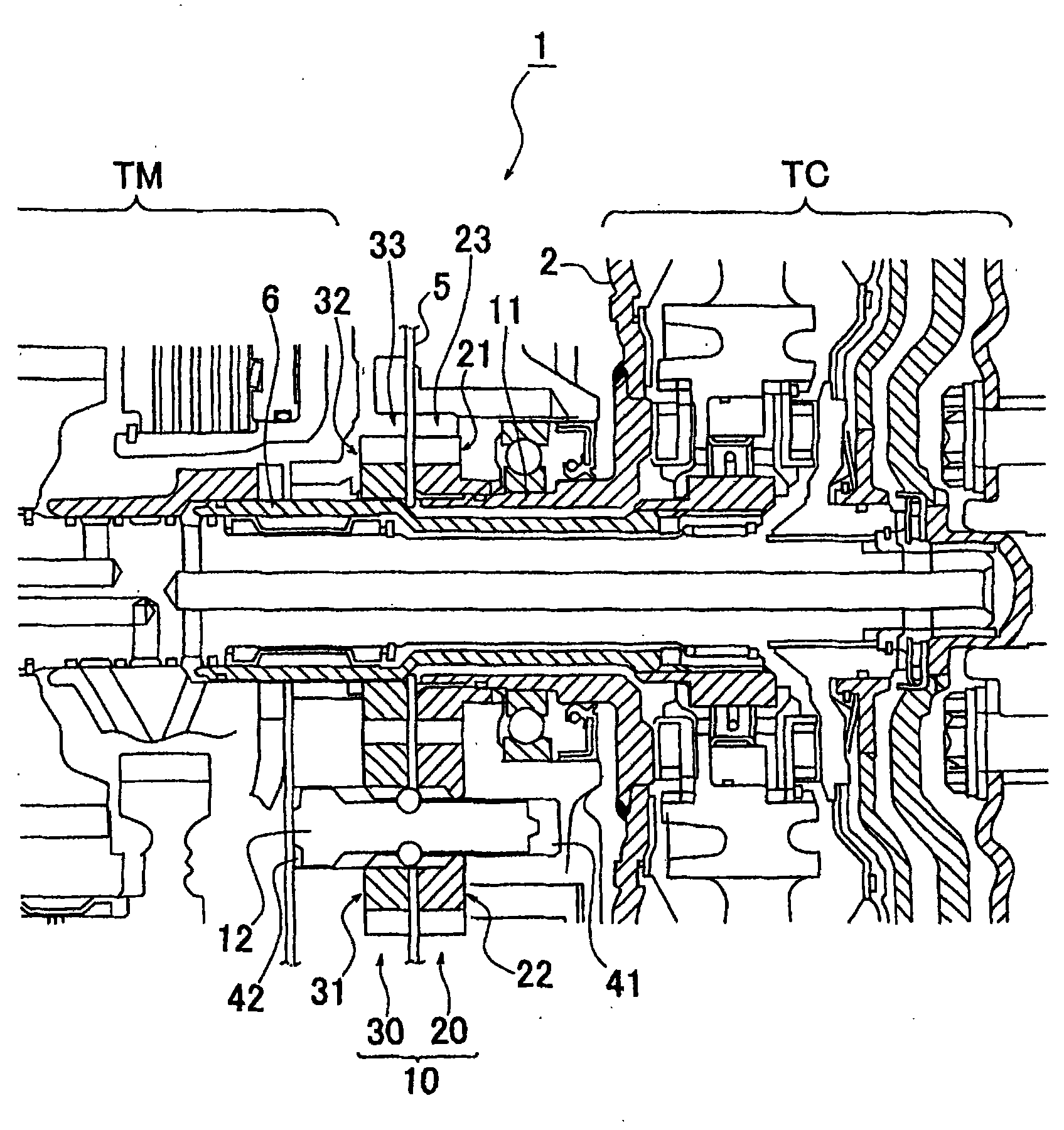
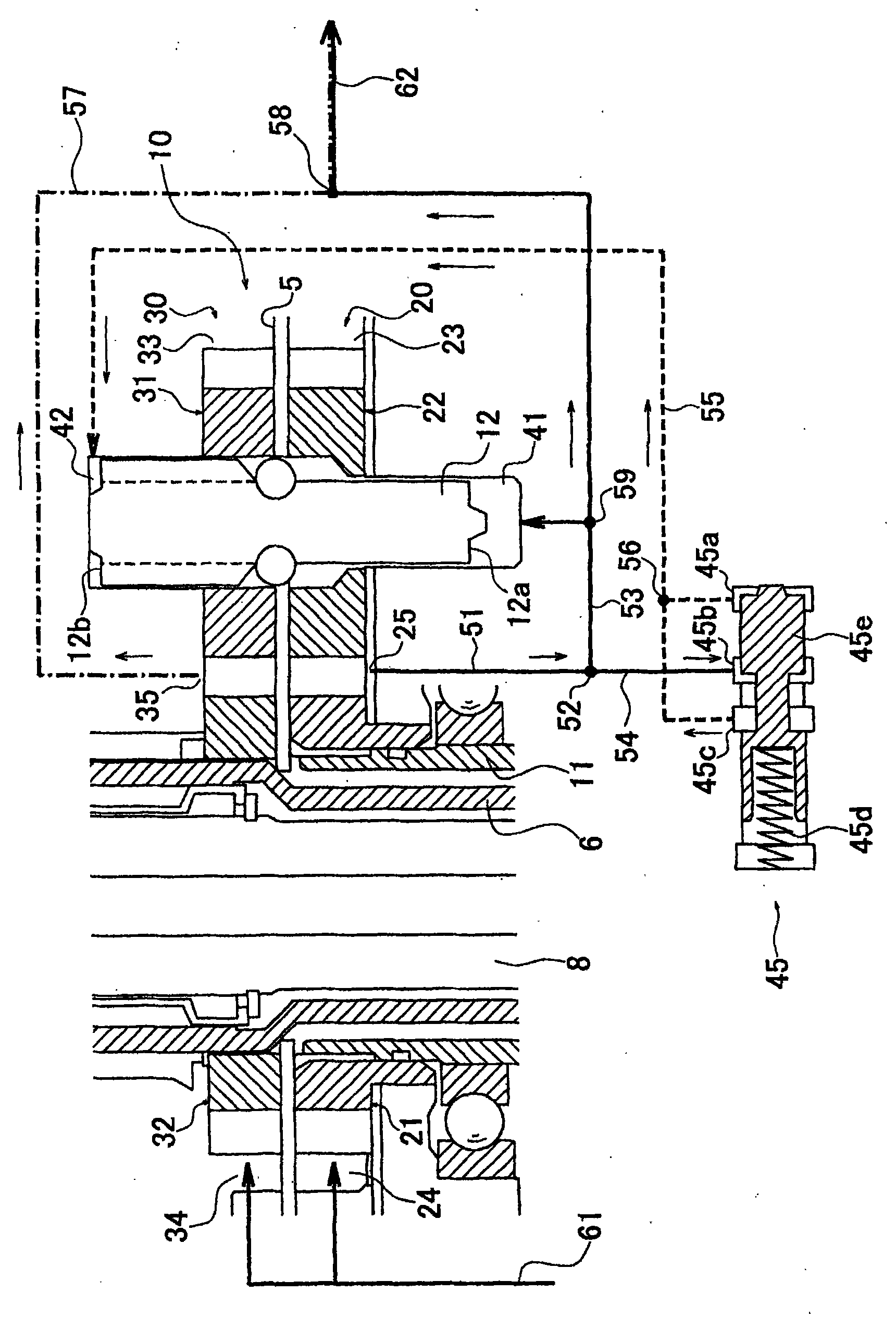
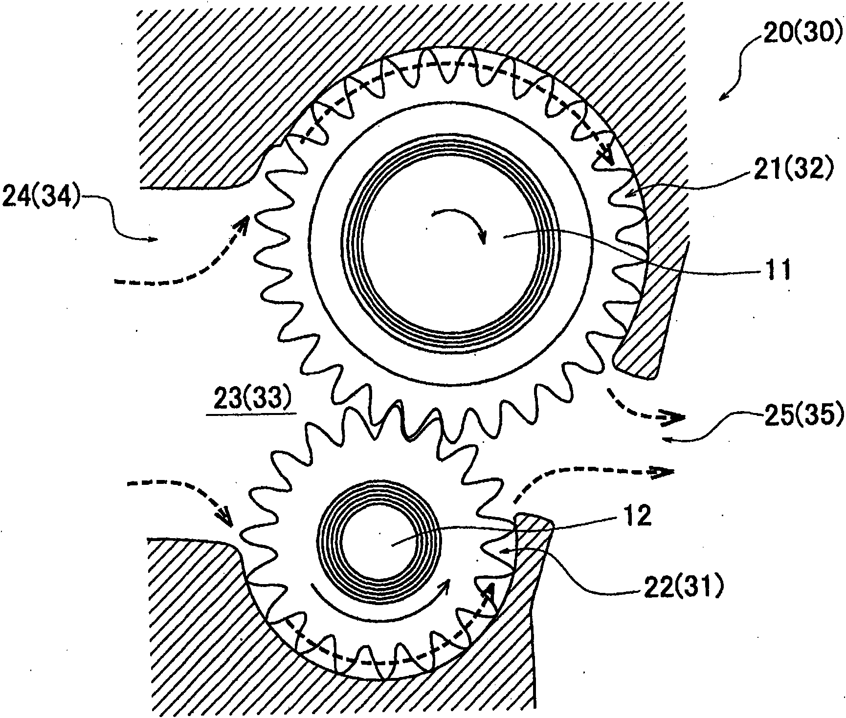
[0026] figure 1 It is a partial side cross-sectional view of an automatic transmission including an oil pump (gear pump) 10 according to the first embodiment of the present invention. and, figure 2 is a side sectional view for explaining the detailed structure of the oil pump 10, image 3 It is a schematic side view of the oil pump 10 viewed from the axial direction of the drive shaft 11 and the rotation shaft 12 described later. figure 1 The illustrated automatic transmission 1 includes a torque converter TC for amplifying and outputting torque input from an engine (not shown), a transmission mechanism TM for realizing predetermined shift speeds, and further includes a torque converter TC for amplifying and outputting torque input to each of the automatic transmission 1 . An oil pump 10 that partially supplies working oil and lubricating oil (hereinafter both are referred to as "working oil").

[0027] Oil pump 10 is provided between torque converter TC and transmission m...


PUM


Abstract

The present invention provides a gear pump with a simple structure and capable of easily regulating the discharging flow rate. The gear pump includes: a first pump (20) constructed from a first drive gear (21) rotated by driving of a drive shaft (11) and a first driven gear (22) rotatably arranged coaxially with a rotary shaft (12); and a second pump (30) constructed from a second drive gear (31) rotatably provided coaxially with the rotary shaft and a second driven gear (32). The rotary shaft allows the first driven gear and the second drive gear to engage with and disengage from each other in a rotation direction by movement to an axial direction. When the discharge pressure is higher than predetermined pressure, rotation of the first driven gear is not transmitted to the second drive gear and only the first pump operates. When the discharge pressure becomes the predetermined pressure or less, the rotation of the first driven gear is transmitted to the second drive gear and the first and the second pumps operate.

Description

technical field [0001] The present invention relates to a gear pump driven by a driving source such as an engine, and specifically relates to a variable displacement gear pump. Background technique [0002] The discharge flow rate of a gear meshing pump is determined by the capacity corresponding to the tooth height and tooth width, and the rotation speed of the gears (pump rotation speed). When such a gear pump is used as an oil pump for a vehicle, since the capacity of the oil pump depends on the engine speed as the driving source, depending on the operating conditions of the vehicle, the discharge flow rate of the oil pump may not reach the required flow rate of the supply part. In some cases, the required amount of oil may not be properly supplied. [0003] Conventionally, in order to cope with such a problem, variable displacement gear pumps disclosed in Patent Documents 1 to 4 have been proposed. The gear pump of Patent Document 1 has an oil pressure regulating valve...

Claims


Application Information

Patent Timeline
Patent Type & Authority Applications(China)
IPC IPC(8): F04C11/00F04C2/18F04C14/00
CPCF04C2270/56F04C11/001F04C14/06F04C15/0057F04C2/14F04B9/02F04C2/18F04C14/16F16D31/04F16D67/00F16H39/36
Inventor 日高祐一
Owner HONDA MOTOR CO LTD
Features
  • R&D
  • Intellectual Property
  • Life Sciences
  • Materials
  • Tech Scout
  • Unparalleled Data Quality
  • Higher Quality Content
  • 60% Fewer Hallucinations
Learn More