Shaft end type torque loader

A torque loader and shaft end technology, applied in the field of mechanical devices, can solve the problems of inability to rotate in a full circle, limited loading angle, etc., and achieve the effects of good versatility, low vibration and noise, and good cold working manufacturability

Inactive Publication Date: 2010-10-13
HARBIN ENG UNIV
View PDF4 Cites 13 Cited by
  • Summary
  • Abstract
  • Description
  • Claims
  • Application Information

AI Technical Summary

Problems solved by technology

High-power loaders imported from abroad generally have limited loading angles and cannot rotate for a full circle

Method used


Image

  • Shaft end type torque loader
  • Shaft end type torque loader
  • Shaft end type torque loader

Examples


Embodiment Construction

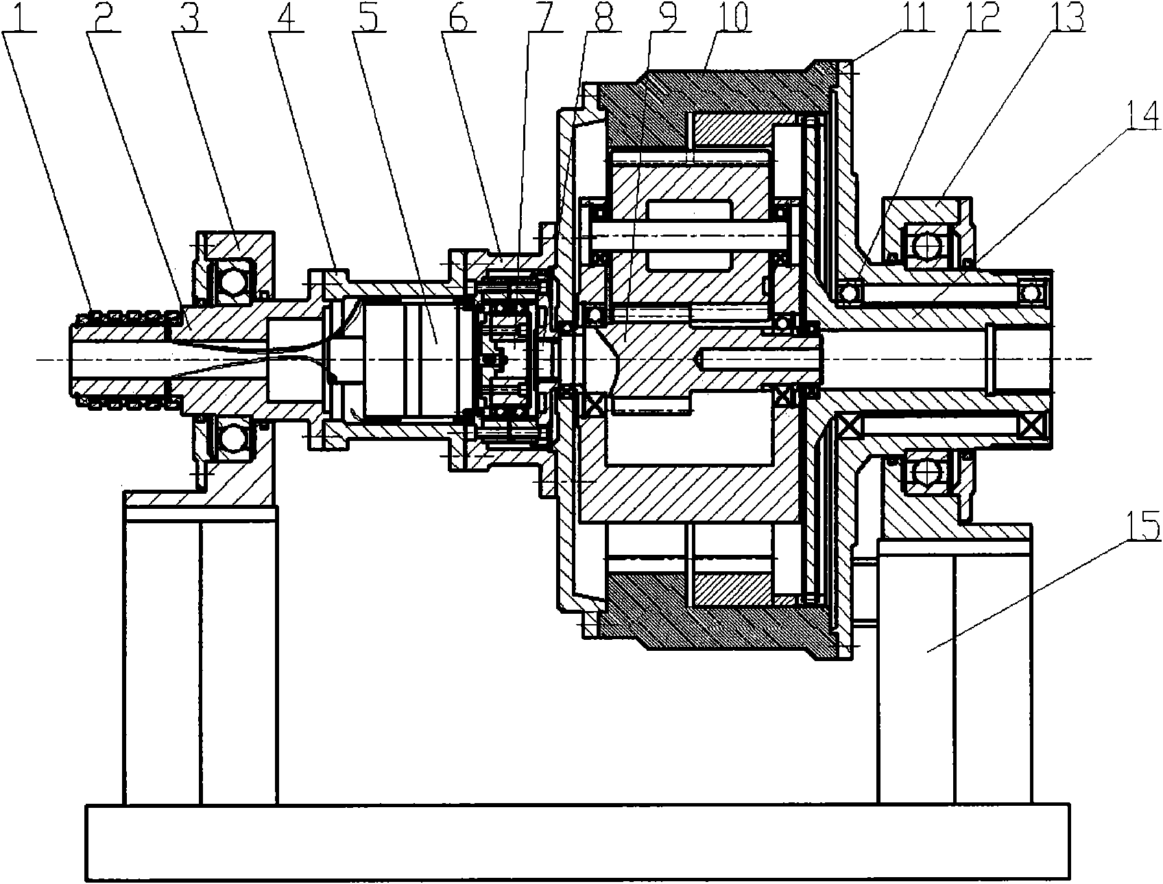
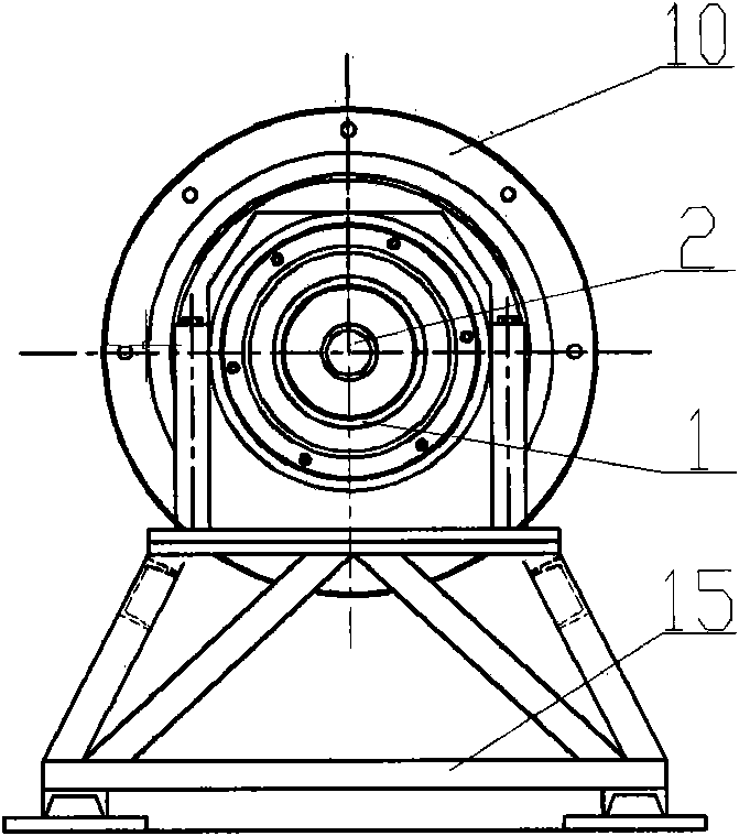
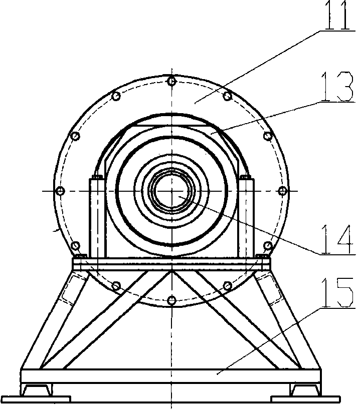
[0015] The present invention is described in more detail below in conjunction with accompanying drawing example:

[0016] combine Figure 1-5 , the present invention consists of collector ring 1, hollow shaft 2, bearing frame 3, drive motor casing 4, drive motor 5, harmonic reducer casing 6, harmonic reducer 7, harmonic reducer output rigid wheel 8, the first planet The gear train reducer input gear shaft 9, the planetary gear train reducer housing 10, the output shaft sleeve 11, the output shaft sleeve bearing 12, the output shaft end bearing frame 13, the output shaft 14, and the base 15 are composed. The collector ring 1 is fitted on the hollow shaft 2 with interference, and the hollow shaft is supported on the bearing frame 3. The hollow shaft 2 is connected with the drive motor housing 4 by bolts through the flange, and the drive motor 5 is fixed inside, and input through the collector ring 1. The electric power connected to the drive motor 5, the drive motor shell 4 and...


PUM


Abstract

The invention aims to provides a shaft end type torque loader, which comprises a collecting ring, a reducer, an input shaft, an output shaft, a drive motor, a base, a bearing bracket arranged outside the input shaft, an output shaft sleeve arranged outside the output shaft, an output shaft end bearing bracket arranged outside the output shaft sleeve, a harmonic reducer shell fixed outside a harmonic reducer and a planetary gear train reducer shell fixed outside a planetary gear train reducer. The collecting ring is sleeved on the input shaft. The input shaft is connected with the drive motor. One end of the harmonic reducer is connected with the drive motor, while the other end thereof is connected with the planetary gear train reducer. The planetary gear train reducer is also connected with the output shaft. Both the bearing bracket and the output shaft end bearing bracket are fixed on the base. The shaft end type torque loader can change the size and the direction of a torque at the closed end, can stably maintain a torque value at the closed end, and has an unlimited travel angle of the loading motion, capability of amplifying physical factors as well as small energy consumption and low vibration and noise in the operating process.

Description

technical field [0001] The present invention relates to a mechanical device for torque loading. Background technique [0002] In the research and development process of the reducer for large mechanical equipment, its performance is often tested through a closed test system. In the closed test system, a loader is used to apply load to the entire test system to simulate the actual working state of the reducer. The load is reflected in the form of power, a large torque is applied by the loader, and the entire test system is equipped with a high speed, so that a large power can be applied to the test system. For the test system, the form of coaxial transmission is adopted. Considering the stable operation and small footprint, the shaft end loading method is often used, that is, the shaft end loader. If the torque range that the loader can apply is large and the loading torque is stable, then the performance of the test system will be excellent and the application range will be ...

Claims


Application Information

Patent Timeline
IPC IPC(8): G01M13/02
Inventor 王立权安永东孙荣华王刚王正博
Owner HARBIN ENG UNIV
Why Eureka
Try Eureka