Check patentability & draft patents in minutes with Patsnap Eureka AI!

Lighting spherical sun position sensor and automatic tracking method

A sun position and automatic tracking technology, applied in the direction of position/direction control, instruments, non-electric variable control, etc., can solve the problems of high system cost, complex structure, energy loss, etc., to reduce energy consumption, reduce manufacturing costs, The effect of simple structure

Active Publication Date: 2010-10-13
溧阳常大技术转移中心有限公司
View PDF5 Cites 11 Cited by
  • Summary
  • Abstract
  • Description
  • Claims
  • Application Information

AI Technical Summary

Problems solved by technology

Since the height and incident angle of sunlight often change throughout the year and every day, the current automatic tracking sunlight system generally uses the action of a worm gear mechanism or a push rod mechanism to achieve synchronous tracking. The defect is: the collection of sunlight It can only be tracked within a certain range of angles, and cannot be automatically tracked all year round and all-weather, and the system cost is high and the structure is complex. At the same time, the system must be continuously detected, and the motor must be continuously adjusted, resulting in a large loss of energy

Method used


Image

  • Lighting spherical sun position sensor and automatic tracking method
  • Lighting spherical sun position sensor and automatic tracking method
  • Lighting spherical sun position sensor and automatic tracking method

Examples


Embodiment Construction

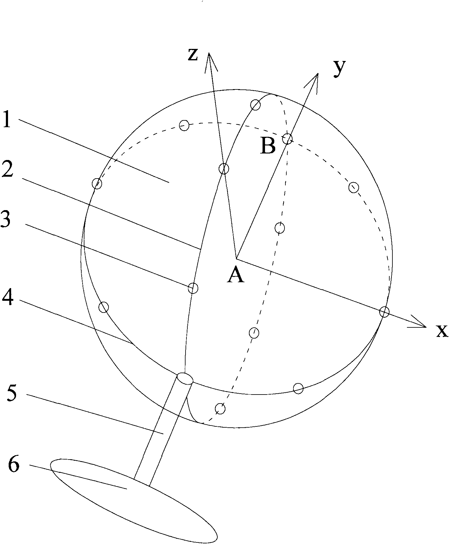
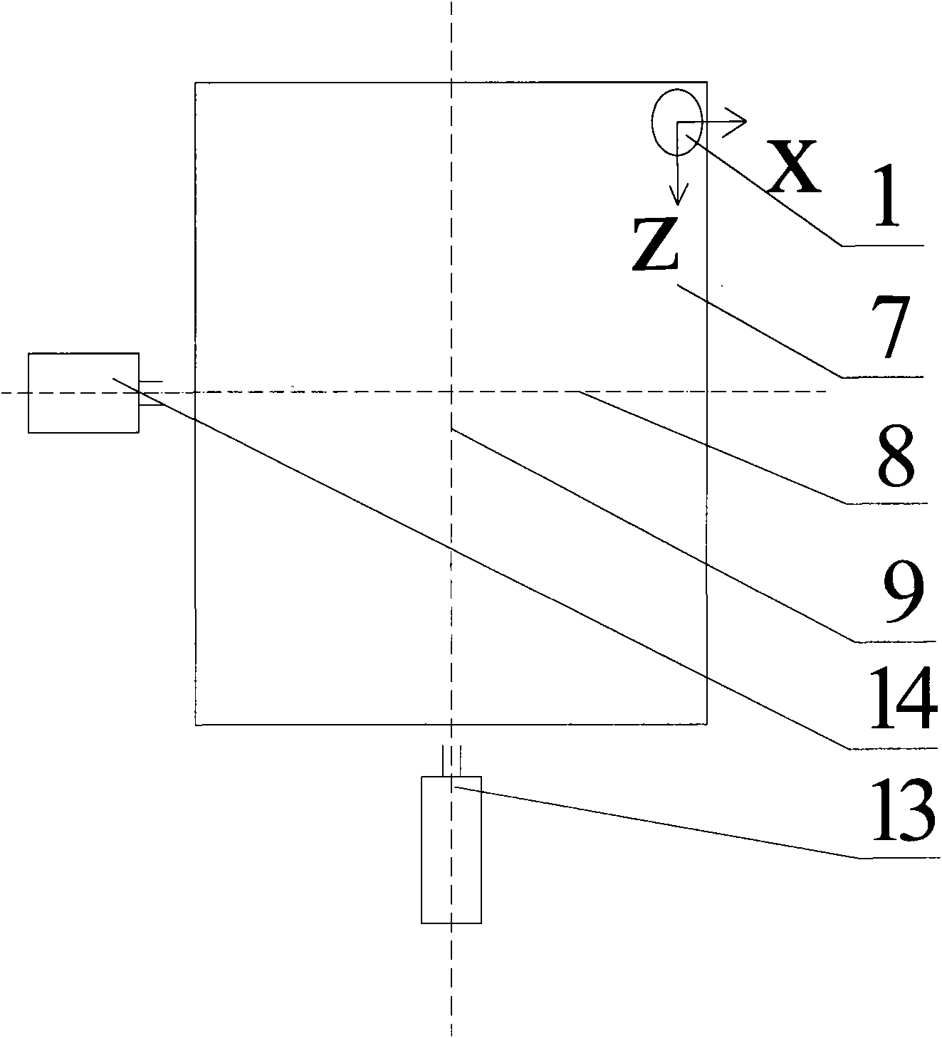
[0013] Such as figure 1 , 2 The sun position sensor shown in and 3 is specifically an opaque spherical base 1. The center point of the spherical base 1 is A, and the mutually perpendicular XY plane and YZ plane passing through the center point A intersect with the spherical base 1 to form two great circles 4 and 1 respectively. 2. In the positive direction of the Y axis, the big circles 4 and 2 intersect at the vertex B of the spherical base 1, and 7-15 high-precision photoresistors 3 are evenly distributed on the circumference of the big circle 2. The vertex B is opposite to the connecting rod 5, and the vertex The bottom of the spherical base 1 corresponding to B does not have a photoresistor 3 installed. The photoresistor 3 at the top B is shared by the two large circles 2 and 4, and there are 13-29 high-precision photoresistors 3 in total. A hollow and slender connecting rod 5 is connected to the bottom of the spherical base 1, and the bottom end of the connecting rod 5 i...


PUM


Abstract

The invention discloses a lighting spherical sun position sensor and an automatic tracking method, which ensure that a panel receiving sunlight always keeps vertical with the sunray. The lighting spherical sun position sensor comprises a non-transparent spherical base body. A plurality of light dependent resistors are respectively distributed on the circumferences of two great circles of the spherical base body, and a base is fixed at one side of the sunlight panel to enable the sunlight panel to rotate with 360 degrees in the horizontal direction and rotate with 90 degrees in the vertical direction under the driving of two direct current motors. The light dependent resistors send sunlight intensity signals to a signal acquisition module, the sunlight intensity signals are processed, and the processed signals are sent to a singlechip control module to determine the position of the sun. A control signal is sent to a PWM (Pulse Width Modulation) speed regulation module to control the actions of the two direct current motors, therefore, the position of the sunlight panel is adjusted. By adopting the invention, the azimuth angle and the elevating angle of the sunlight can be automatically tracked with high precision and short time, the energy consumption for real-time tracking can be reduced with simple structure, and the production and manufacturing cost can be reduced.

Description

technical field [0001] The invention relates to the field of solar energy collecting devices, in particular to a daylighting spherical sun position sensor, which can keep a panel receiving sunlight perpendicular to the sunlight at all times. Background technique [0002] Solar energy has become a widely used clean energy. There are more and more types of products using solar energy. However, many products still use a fixed orientation to collect sunlight. Because the incident angle of sunlight is sometimes large, the utilization rate of solar energy is low. In order to improve the utilization rate of sunlight collection on the collection panel with the same area, it is necessary to automatically track the sunlight so that the sunlight always shines directly on the panel. Since the height and incident angle of sunlight often change throughout the year and every day, the current automatic tracking sunlight system generally uses the action of a worm gear mechanism or a push rod...

Claims


Application Information

Patent Timeline
Patent Type & Authority Applications(China)
IPC IPC(8): G05D3/00
Inventor 葛乐通徐晓东蒋益兴
Owner 溧阳常大技术转移中心有限公司
Features
  • R&D
  • Intellectual Property
  • Life Sciences
  • Materials
  • Tech Scout
  • Unparalleled Data Quality
  • Higher Quality Content
  • 60% Fewer Hallucinations
Learn More