Three-state three-level PFC circuit and multi-state three-level PFC circuit

A three-level, circuit technology, applied in the field of electronics, can solve the problem that the PFC circuit cannot improve the efficiency and power density at the same time, and achieve the effects of reducing the switching frequency, reducing the size of the inductance and high circuit efficiency.

Active Publication Date: 2010-10-13
EMERSON NETWORK POWER CO LTD
View PDF4 Cites 33 Cited by
  • Summary
  • Abstract
  • Description
  • Claims
  • Application Information

AI Technical Summary

Problems solved by technology

[0005] The technical problem to be solved by the present invention is to provide a three-state three-level PFC circuit and a multi-state three-level PFC circuit for the above-mentioned defects that the existing PFC circuit cannot simultaneously improve the efficiency and power density

Method used


Image

  • Three-state three-level PFC circuit and multi-state three-level PFC circuit
  • Three-state three-level PFC circuit and multi-state three-level PFC circuit
  • Three-state three-level PFC circuit and multi-state three-level PFC circuit

Examples


Embodiment Construction

[0044] In order to make the object, technical solution and advantages of the present invention clearer, the present invention will be further described in detail below in conjunction with the accompanying drawings and embodiments.

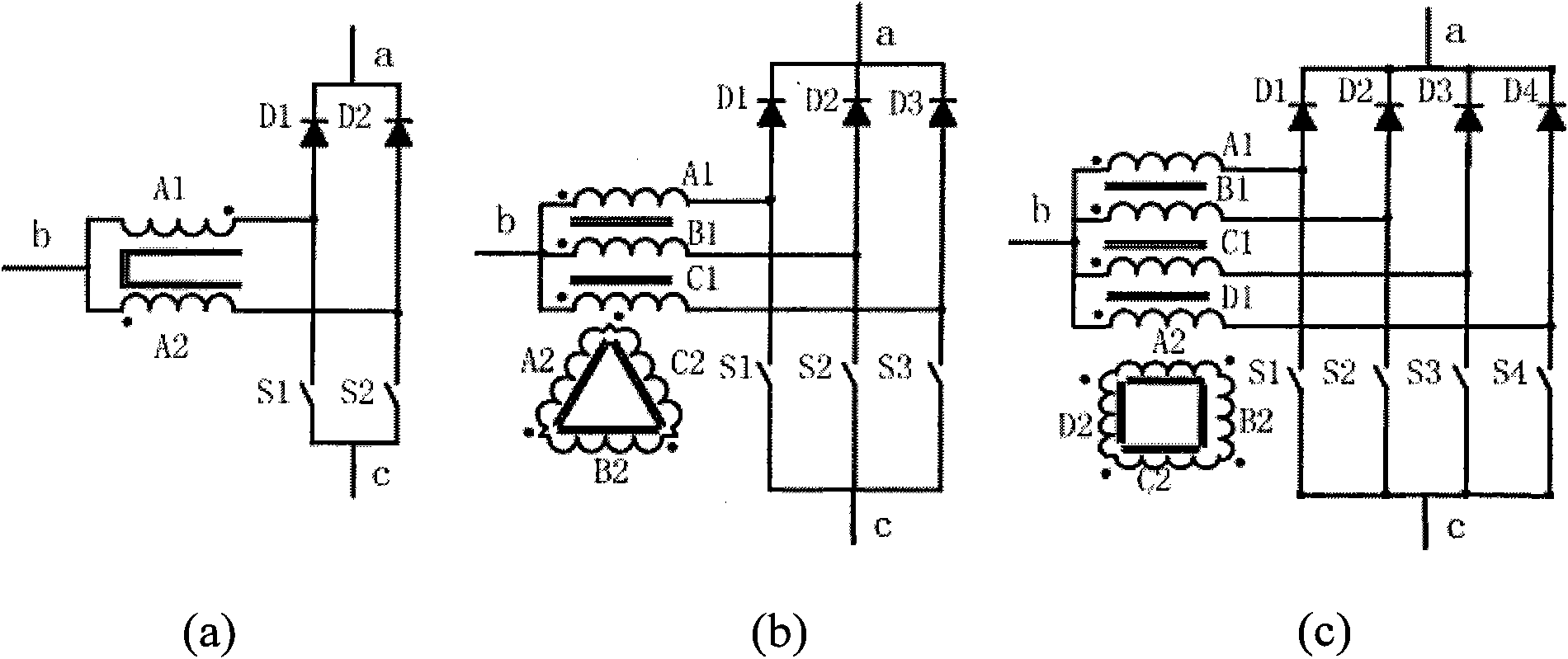
[0045] The invention mainly applies the three-state switch and the multi-state switch to the PFC circuit to realize the output of the three-state or multi-state three-level circuit. The definition of the multi-state switch is described below. see figure 2 (a) to figure 2 (c), are the structural schematic diagrams of three-state switch, four-state switch and five-state switch, respectively. To realize the structure of the multi-state switch, a transformer and a bridge arm composed of a switch tube and the like are required. Such as figure 2 As shown in (a), if there are two windings on the primary side of the transformer, the switching tube is a two-arm structure, and what is realized is a three-state switch; as figure 2 As shown in (b), if...


PUM


Abstract

The invention relates to a three-state three-level PFC circuit, which comprises an inductor, a combined three-state switch, a first capacitor and a second capacitor. The inductor is connected between a first end of an AC power supply and a first end of the combined three-state switch; a second end of the combined three-state switch is connected at a first end of the first capacitor; a third end of the combined three-state switch is connected at a second end of the second capacitor; a fourth end of the combined three-state switch is grounded; and the first end of the first capacitor, a second end of the first capacitor, and the second end of the second capacitor output three-level voltage. The invention also provides a multi-state three-level PFC circuit correspondingly. Compared with the common circuit without a three-state switch or a multi-state switch, the PFC circuit provided by the invention can obviously reduce the dimensions of the inductor and the capacitors, improve the powerfactor of the circuit simultaneously and reduce the total harmonic content on the premise of maintaining the switch frequency and ripples on a passive device invariable, and can reduce the switch frequency and obviously improve the circuit efficiency on the premise of maintaining the input current ripple frequency and magnitude invariable.

Description

technical field [0001] The invention relates to the field of electronic technology, and more specifically relates to a three-state three-level PFC circuit and a multi-state three-level PFC circuit. Background technique [0002] High-frequency switching power supplies are widely used in different occasions, such as the need to change the power supply voltage from one voltage level to another required voltage level under many application conditions. In this AC to DC (AC / DC) conversion system, in addition to the required voltage conversion function, it is also necessary to meet various standards for power factor (Power Factor, PF), total harmonic content (Total Harmonics Distortion, THD) and EMI (Electromagnetic Interference) requirements. [0003] see figure 1 , is a three-level PFC circuit. Such as figure 1 As shown, the first end of the inductor L1 is connected to the first end of the AC power supply, and the second end of the inductor L1 is connected to the first input ...

Claims


Application Information

Patent Timeline
Patent Type & Authority Applications(China)
IPC IPC(8): H02M1/42
CPCY02B70/126H02M1/4225Y02B70/10H02M1/0064
Inventor 弗兰克·赫尔特孟丽婵武志贤
Owner EMERSON NETWORK POWER CO LTD
Why Eureka
Try Eureka