Turn-on angle control method for switched reluctance motor

A technology of switched reluctance and control methods, applied in current controllers, electronic commutators, etc., can solve the problems of large amount of calculation, complicated process, lack of versatility, etc., and achieve simple and easy algorithm, convenient transplantation, Versatility and adaptability

Active Publication Date: 2012-10-31
SHANDONG KEHUI POWER AUTOMATION
View PDF0 Cites 0 Cited by
  • Summary
  • Abstract
  • Description
  • Claims
  • Application Information

AI Technical Summary

Problems solved by technology

[0003] 1. The calculation of the table required for the preparation of the search is large and the process is complicated;
[0004] 2. The large amount of table data requires additional storage space, and frequent table lookup operations reduce the performance of the control system;
[0005] 3. It is only established for the specific motor object of the experiment. It is not universal to change the motor model or even a different motor of the same type. It needs to be measured again.

Method used


Image

  • Turn-on angle control method for switched reluctance motor
  • Turn-on angle control method for switched reluctance motor
  • Turn-on angle control method for switched reluctance motor

Examples


Embodiment Construction

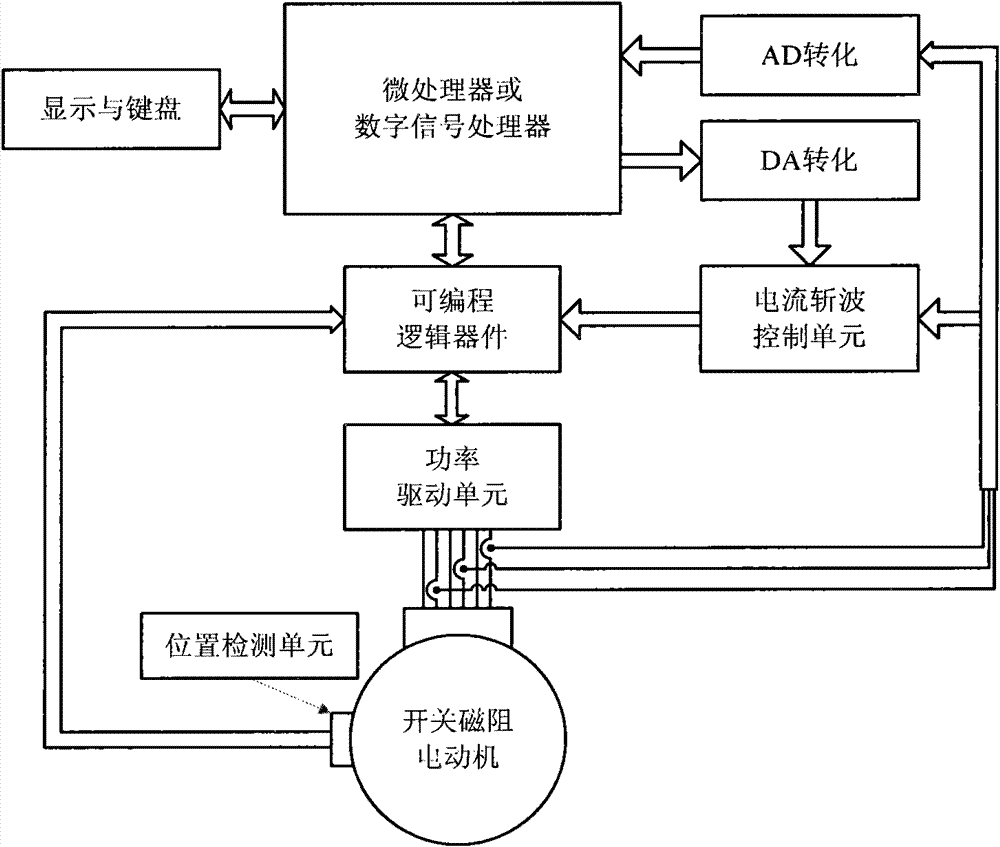
[0031] Attached figure 1 Attached Image 6 The technical scheme of the present invention is described in detail:

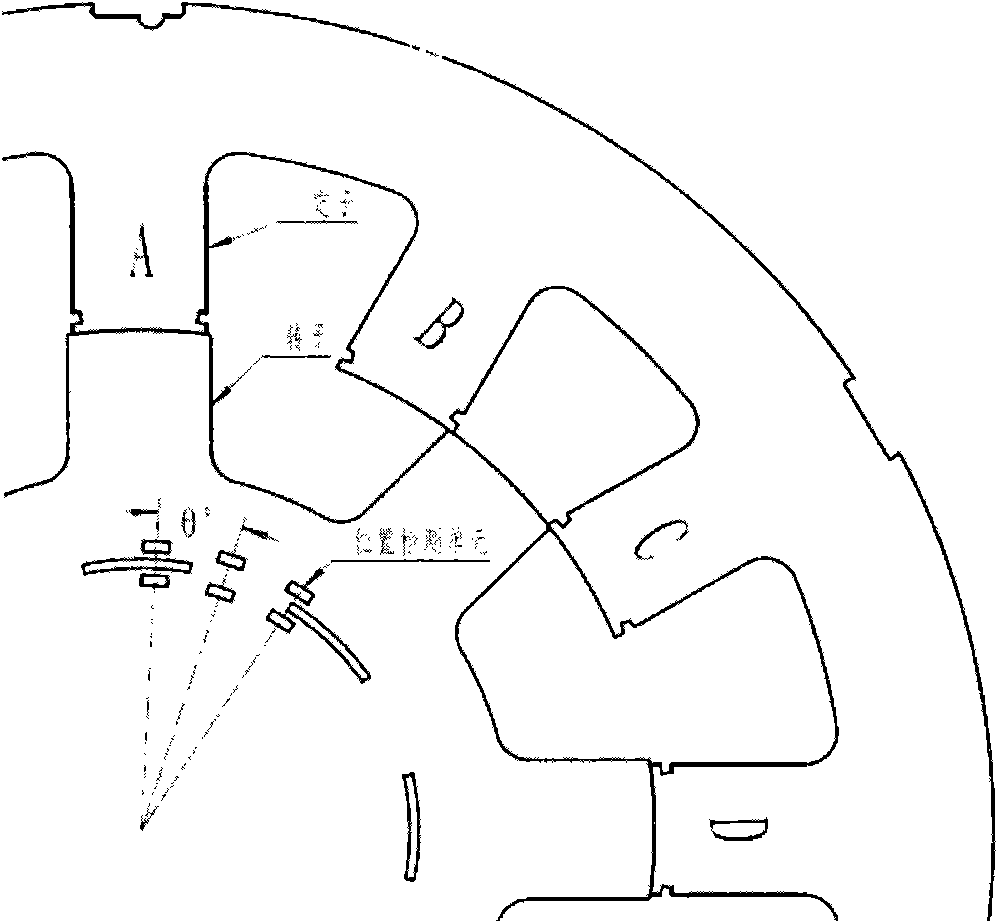
[0032] 1. Determination of the angle between the sensors: according to the formula Calculate the angle between the sensors, where m is the phase number of the switched reluctance motor, N s Is the number of stator poles, N r Is the number of rotor poles. For a 12 / 8-pole switched reluctance motor, taking into account factors such as cost and implementation complexity, k is 0, θ g Take 15°. The sensor can choose photoelectric sensor or Hall sensor. Such as figure 2 Shown

[0033] 2. The steps to determine the relative position of the position detection unit and the shielding disc of the switched reluctance motor are: energize one phase winding of the switched reluctance motor, make the stator and rotor of this phase aligned, and set the sensor at the shielding position signal as 1. The non-shading position signal is 0. Adjust the relative position of the position d...


PUM


Abstract

The invention discloses a turn-on angle control method for a switched reluctance motor, belonging to the technical field of angle control of switched reluctance motors. The invention provides an optimized control method for a turn-on angle based on characteristics of the switched reluctance motor. The method is realized by a position detection unit: a position level signal is generated by the position detection unit and then is encoded by a programmable logic device; and by using a microprocessor, actual rotate speed of the motor is calculated based on the position code, target current value required to conducting a phase winding by the switched reluctance motor is calculated by a PI algorithm, and angle position control is realized based on the target current value, an actual sampling current value and the actual rotate speed value by a special algorithm. The invention can realize automatic setting of the turn-on angle of the switched reluctance motor, improve control flexibility of the switched reluctance motor and simplify design of control program.

Description

Technical field [0001] The invention relates to a method for controlling the opening angle of a switched reluctance motor, and belongs to the technical field of angle control of a switched reluctance motor. Background technique [0002] There are three main control methods of switched reluctance motors: current chopping control (CCC), voltage chopping control (PWM), and position angle control (APC). Among them, the position angle control (APC) realizes the control of the motor by setting the opening and closing angles. When the motor is running, the influence of the cut-off angle on the motor is smaller than that of the switch-on angle. Therefore, the method of fixing the cut-off angle and controlling the switch-on angle is generally used to realize motor control. Traditional opening angle control needs to measure the flux linkage characteristics of the switched reluctance motor during operation, and use complicated partial differential equations to derive the opening angles at ...

Claims


Application Information

Patent Timeline
Patent Type & Authority Patents(China)
IPC IPC(8): H02P6/16H02P6/28
Inventor 徐丙垠熊立新张明魁刘志宏
Owner SHANDONG KEHUI POWER AUTOMATION
Why Eureka
Try Eureka