
Fuel cell system

A fuel cell system and fuel cell technology, applied in the direction of fuel cells, fuel cell additives, transportation fuel cell technology, etc., can solve the problems of the height and size of the casing, the increase of the height and size of the casing, etc.

Active Publication Date: 2013-03-13
TOYOTA JIDOSHA KK
View PDF2 Cites 0 Cited by
  • Summary
  • Abstract
  • Description
  • Claims
  • Application Information

AI Technical Summary

Problems solved by technology

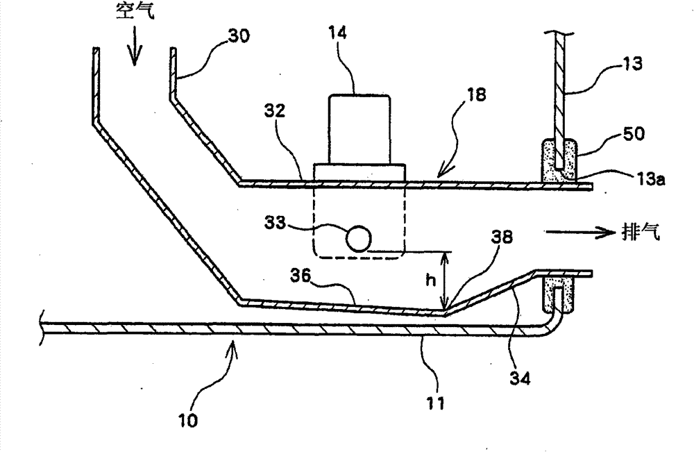
[0009] However, when the diluter is accommodated in the fuel cell case with the aforementioned height difference of tens of centimeters, the height of the case increases.
In addition, for the diluter, it is also necessary to maintain a large internal space for sufficient mixing and dilution, resulting in an increase in size. Therefore, when the fuel cell case is mounted under the bottom plate, accommodating the diluter in the case will prevent the case from High Dimension Barriers

Method used


Image

  • Fuel cell system
  • Fuel cell system
  • Fuel cell system

Examples


Embodiment Construction

[0032] Hereinafter, embodiments of the present invention will be described in detail using the drawings. In this description, specific shapes, materials, and the like are examples for easy understanding of the present invention, and may be appropriately changed according to applications, purposes, specifications, and the like.

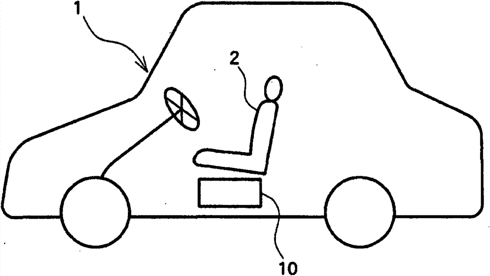
[0033] figure 1 It is a diagram showing a schematic configuration of a fuel cell vehicle 1 including a fuel cell system according to an embodiment of the present invention. In the fuel cell vehicle 1 , a fuel cell case (hereinafter referred to as “FC case”) 10 , which is a component of the fuel cell system, is mounted on the lower portion of the floor below the front seat 2 .

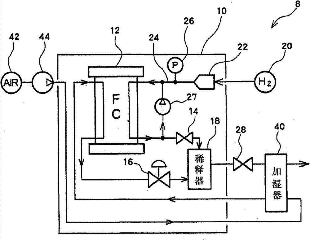
[0034] figure 2 A schematic configuration of the fuel cell system 8 of the present embodiment is shown. figure 2 This is the state of the fuel cell system 8 seen from above. The fuel cell system 8 includes elements such as a fuel cell stack 12 as a fuel cell housed in the...


PUM


Abstract

A fuel cell system which can encase a dilution device while keeping the height of a fuel cell case as low as possible by utilizing the lower space in the case effectively. A fuel cell system comprises a fuel cell stack generating power through an electrochemical reaction between a gas supplied to the anode side and a gas supplied to a cathode side, a dilution device for diluting an anode off gas discharged from the fuel cell stack with a cathode off gas and discharging the diluted gas, and a fuel cell case for encasing the fuel cell stack and the dilution device. In this fuel cell system, a lateral opening of the fuel cell case for passing an exhaust pipe extending to the exhaust downstream of the dilution device is arranged above the lowermost portion of the inner surface of the dilution device with respect to the gravitational direction.

Description

technical field [0001] The present invention relates to a fuel cell system, and more particularly to an exhaust device associated with a diluter that dilutes and exhausts anode off-gas exhausted from a fuel cell stack. Background technique [0002] In recent years, fuel cell stacks have been mounted on automobiles or vehicles because they have little impact on the environment. In a fuel cell stack, for example, a fuel gas such as hydrogen is supplied to the anode side of the fuel cell, and an oxygen-containing oxidizing gas such as air is supplied to the cathode side, and necessary power is extracted by an electrochemical reaction through an electrolyte membrane. [0003] The cathode off-gas when the oxidizing gas supplied to the cathode side is discharged from the fuel cell stack contains reaction product water generated by the electrochemical reaction. On the other hand, the anode off-gas when the fuel gas supplied to the anode side is discharged from the fuel cell stack ...

Claims


Application Information

Patent Timeline
Patent Type & Authority Patents(China)
IPC IPC(8): H01M8/04H01M8/06H01M8/00H01M8/10
CPCY02T90/32H01M2250/20B60L11/1887H01M8/04179Y02E60/50Y02T90/40
Inventor 片野刚司
Owner TOYOTA JIDOSHA KK
Learn More