
Oil pump device of pipe cutter

A pipe cutting machine and oil pump technology, which is applied in the field of oil pumps, can solve the problems that the jack cannot achieve fast feed, the machine cannot work normally, and the pressure cannot be adjusted, so as to achieve the effects of compact structure, improved life, and preventing oil from entering the oil cylinder

Inactive Publication Date: 2010-10-20
HANGZHOU HONGLI PIPE MACHINERY
View PDF0 Cites 2 Cited by
  • Summary
  • Abstract
  • Description
  • Claims
  • Application Information

AI Technical Summary

Problems solved by technology

The oil pump and cylinder of the 258 electric pipe cutting machine are connected by high-pressure oil pipes, and the pressure required for work is relatively high, which has high requirements for pipes and seals. This model is a movable electric tool. It is very easy to cause oil leakage due to twisting of the hose, resulting in pressure loss and the machine cannot work normally
Because domestic manufacturers cannot meet the technical requirements, they have to use mature jacks to replace this set of oil pumps and oil cylinders, but the jacks cannot achieve fast feed, and the force direction is not perpendicular to the knife arm. Caused by power loss, pressure can not be adjusted and other defects , the structure is not compact, and the appearance is rough, which makes customers complain

Method used


Image

  • Oil pump device of pipe cutter
  • Oil pump device of pipe cutter
  • Oil pump device of pipe cutter

Examples


Embodiment Construction

[0020] Below in conjunction with accompanying drawing, patent of the present invention is described further.

[0021] see figure 1 , figure 2 , image 3 , Figure 4 :

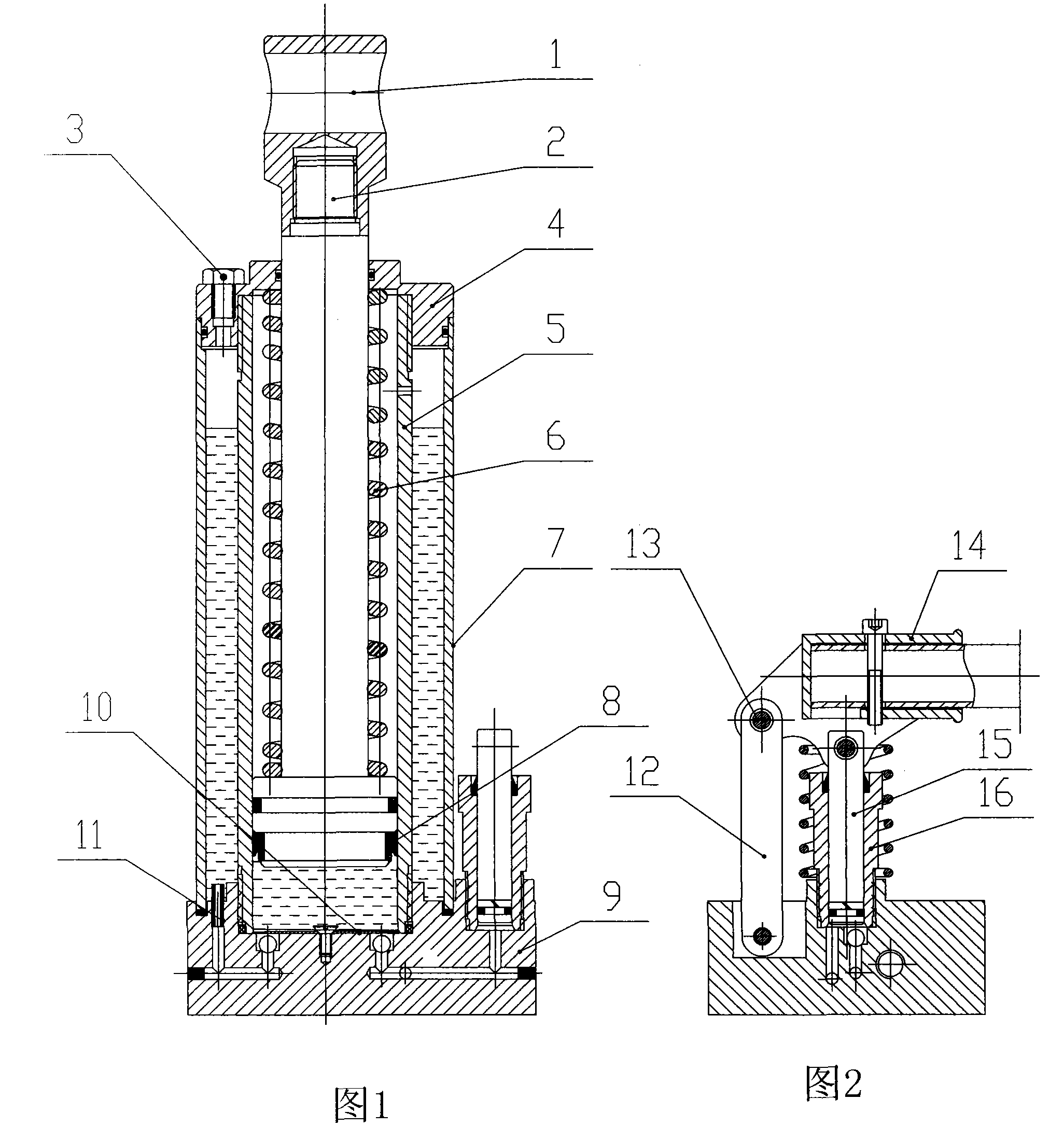
[0022] The oil pump invented this time is mainly composed of the following structures: hydraulic plug 1, piston 2, ventilation screw 3, top cover 4, cylinder body 5, compression spring 6, cylinder body 7, sealing ring 8, base 9, pressure plate 10, plastic soft Pipe 11, pole 12, pin 13, handle 14, small piston 15, pump body 16,

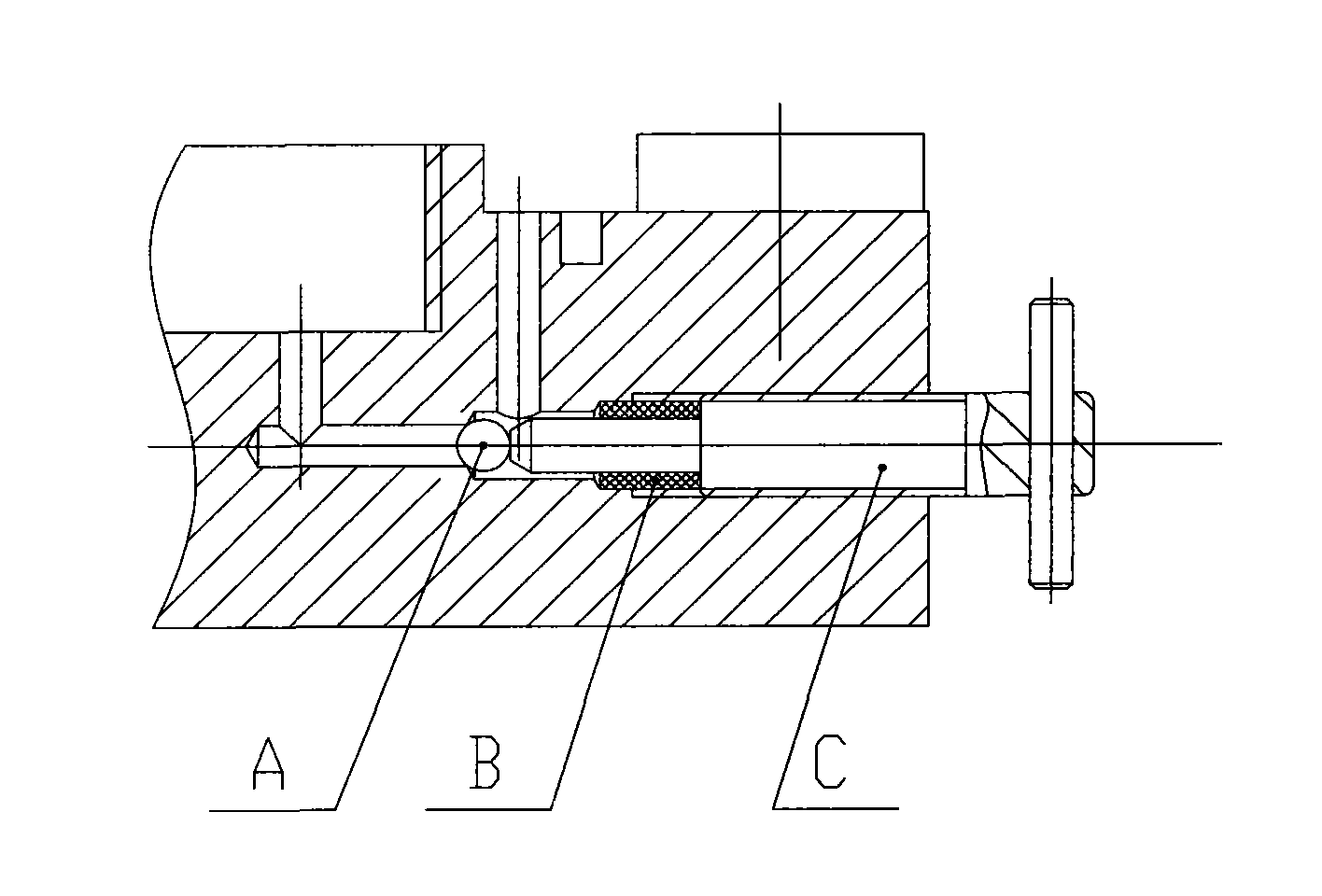
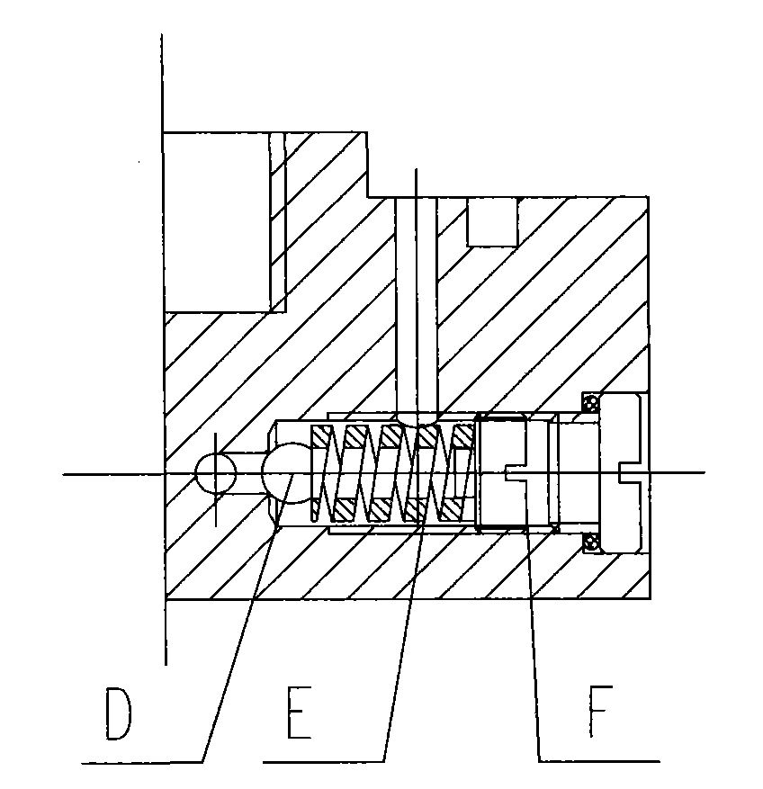
[0023] image 3 oil return circuit and Figure 4 The pressure regulating oil circuit, as well as other seals and standard parts.

[0024] The oil return route is composed of A. steel ball, B. sealing sleeve, and C. jacking screw, and the jacking screw passes through the sealing sleeve to top the steel ball.

[0025] The pressure regulating oil is composed of D. steel ball E. rectangular compression spring F. adjustment screw, and the adjustment screw, rectangular compression sp...


PUM


Abstract

The invention relates to an oil pump device of a pipe cutter, which comprises a hydraulic top head, a piston, an air vent screw, a top cover, a cylinder body, a compression spring, a barrel body, a seal ring, a base, a pressure plate, a support rod, a pin, a handle, a small piston and a pump body, wherein the cylinder body is installed on the base by threaded connection, the barrel body is sheathed at the outer ring of the cylinder body, the top cover is tightly screwed on the cylinder body by a thread, and simultaneously the barrel is compressed; the piston and the seal ring form a piston rod assembly, the compression spring is sheathed on the piston rod, the hydraulic top head is installed on the piston, the piston rod assembly is installed in the cylinder body, the lateral side of the barrel body on the base is provided a small manual pump comprising the support rod, the pin, the handle, the small piston and the pump body, the support rod is connected with the handle by the pin, the small piston in the pump body is connected with the handle, a pressure-regulating oil way is added on the pump body, and a return pipeline of the pump is provided with a return oil way; and the air vent screw is fixed in an air vent at one side of the top cover, and the pressure plate at the bottom of the piston is fixed on the based by screws. The oil pump device has the advantages of compact structure, stable quality, low failure rate and convenient maintenance and repair.

Description

technical field [0001] The invention belongs to the oil pump on the pipe cutting machine, which replaces the oil pump and the oil cylinder assembly on the similar foreign pipe cutting machines, and realizes the upward and downward movement of the cutter arm to achieve the purpose of pipe cutting. The oil pump of the present invention adopts a built-in oil circuit, which reduces problems such as loss of pressure caused by loose connection of the pipeline, failure to work normally, and the like. Background technique [0002] The pipe cutting machine is used to cut the pipe fittings. In the past, the pipe fittings were mainly cut by the cutting machine. Due to the limitation of the diameter of the grinding wheel, the pipes above 8″ cannot be cut. Large-scale pipe fittings need to be completed with the help of large-scale special equipment. Foreign 258 electric The pipe cutting machine performs ring cutting by rotating the pipe fittings, which greatly reduces the downward moveme...

Claims


Application Information

Patent Timeline
Patent Type & Authority Applications(China)
IPC IPC(8): B23D21/00B23D33/00
Inventor 梁桂平
Owner HANGZHOU HONGLI PIPE MACHINERY
Learn More