
Method and device for cutting prepreg

A prepreg and cutting technology, which is applied in metal processing and other directions, can solve the problems of increased cost of thin substrate technology, affecting processing quality, and reducing production efficiency, so as to eliminate dust from broken semi-cured resin and resin glass fiber, and improve the sanitation of the working environment , The effect of high cutting size precision

Inactive Publication Date: 2012-07-04
HUAZHONG UNIV OF SCI & TECH
View PDF0 Cites 0 Cited by
  • Summary
  • Abstract
  • Description
  • Claims
  • Application Information

AI Technical Summary

Problems solved by technology

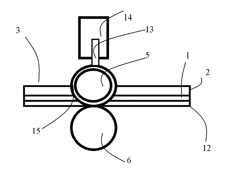
[0004] (1) During the cutting and slitting process, under the thrust of the cylinder 14, the blade 15 of the wheel cutter group 5 collides with the idler roller 6 with high surface hardening strength, which will cause curling, thereby causing the knife edge of the wheel cutter group 5 passivation;
[0005] (2) The width of the edge 15 of the curled edge will increase due to the passivation of the edge, which will increase the width of the prepreg after cutting and slitting, and the edge will scatter, resulting in poor quality of the edge of the incision, which directly affects the quality of subsequent processing. The quality of subsequent products must be checked. and processing, resulting in reduced production efficiency;
[0006] (3) If the area of ​​the edge of the incision is large and the fluff increases, the dimensional accuracy of the cut substrate will be deteriorated and scrapped, which cannot be recycled and reused, resulting in an increase in the cost of purely mechanical cutting of thin substrates;
[0007] (4) The broken semi-cured resin and resin glass fiber dust produced will directly pollute the sanitation of the working environment, affect the health of the operators and the clean production of the slitting workshop

Method used


Image

  • Method and device for cutting prepreg
  • Method and device for cutting prepreg
  • Method and device for cutting prepreg

Examples


Embodiment Construction

[0021] The method that the edge of the wheel knife of the present invention does not curl and passivate during the strip cutting and striping process is shown in Figure 4 As shown in the longitudinal sectional view, in the cutting and slitting process, the blade 15 of the wheel knife 5 is always pierced through the upper layer of epoxy resin 2 and glass cloth base of the prepreg 3 in contact with the blade 15 of the wheel knife 5 1. Only penetrate but not penetrate the lower epoxy resin 12 of the semi-curing agent in contact with the roller 6, so that the blade 15 of the wheel knife 5 does not contact the roller during the cutting and slitting process, thus ensuring The blade 15 of the wheel cutter 5 will not be curled and passivated, and will remain sharp. At the same time, the epoxy resin of the semi-curing agent is used to be more brittle, and the epoxy resin 2 of the semi-curing agent and the glass cloth base 1 are cut and mixed with the semi-curing agent. After the epoxy...


PUM


Abstract

The invention discloses a method and a device for cutting a prepreg. The method is characterized in that: in the cutting and slitting process, the blade of a flywheel knife is always cut through upper-layer epoxy resin and a glass fabric base of a semi-curing substrate contacted with the blade of the flywheel knife, is only penetrated into but not cut through lower-layer epoxy resin of a semi-curing agent contacted with a carrier roller or a riding wheel, so that the blade of the flywheel knife is not contacted with the carrier roller or the riding wheel in the cutting and slitting process. The device comprises a plurality of sets of flywheel knife groups arranged on the same slide guide, wherein the flywheel knife group comprises a flywheel knife, a cylinder, a connecting rod, a micro-adjustment mechanism, a closed bearing, a base and a knife rest, and the gap between the flywheel knife and the carrier roller or the riding wheel is adjusted by the micro-adjustment mechanism. The invention has small width of the cut kerfs and high precision of cutting size, and the edges are not spread out, so the quality of the edges of the kerfs can not be poor. The invention can also reduce or even eliminate the crushed semi-cured resin and resin glass fiber dust generated in the cutting process, improve the sanitation of work environment, and ensure the health of operators and the clean production of slitting workshops.

Description

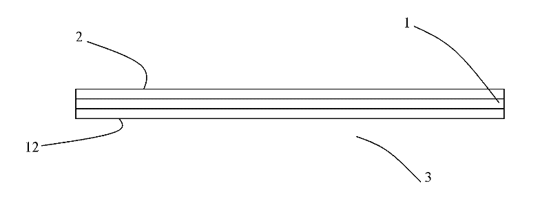
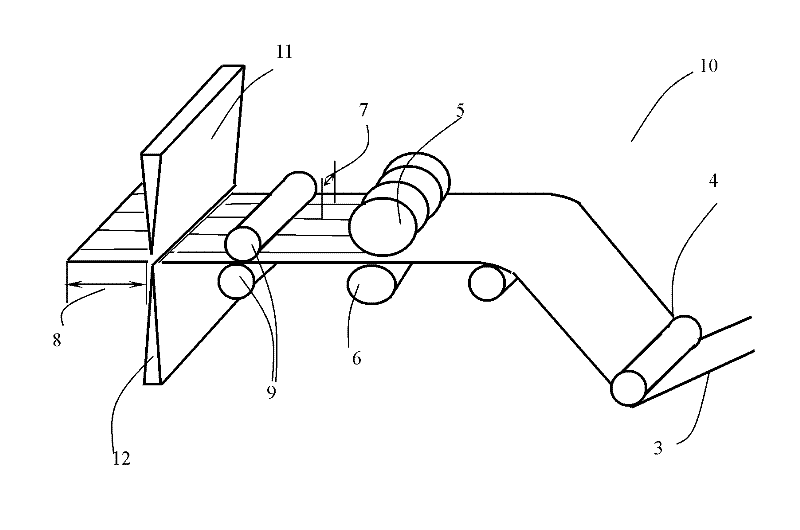
technical field [0001] The invention belongs to the manufacturing technology of printed circuit boards, and in particular relates to a method and a device for cutting a prepreg (substrate material of a printed circuit board made of resin glass fiber cloth). Background technique [0002] Common rigid printed circuit boards (PCB) and copper clad boards (CCL) are basically epoxy resin glass cloth-based double-sided printed circuit boards, and the substrate used is made of glass cloth Layer), pre-impregnated with epoxy resin or other resin with semi-curing agent, after rolling, the epoxy resin of semi-curing agent is cured on both sides of the glass cloth base 2, 12 to form a thinner (thickness of 0.02-0.5mm) Semi-cured resin glass fiber cloth (prepreg P.P) substrate 3, such as figure 1 shown. Then, through the PP slitting and cutting machine, the pieces are cut into the required size. Its cutting process is as figure 2 As shown, the semi-cured resin glass fiber cloth base ...

Claims


Application Information

Patent Timeline
Patent Type & Authority Patents(China)
IPC IPC(8): B26D1/22B26D7/26
Inventor 段军曾晓雁胡乾午王泽敏李祥友
Owner HUAZHONG UNIV OF SCI & TECH
Learn More