Hydraulic operation triple pump hydraulic system

A technology of hydraulic system and triple pump, applied in the field of hydraulic system, can solve the problems of increased operation fatigue, large and complicated system pipelines, slow movement, etc.

Active Publication Date: 2010-10-20
卢宇
View PDF5 Cites 11 Cited by
  • Summary
  • Abstract
  • Description
  • Claims
  • Application Information

AI Technical Summary

Problems solved by technology

[0003] At present, the hydraulic system with many cranes adopts a multi-actuator parallel system, that is, the hydraulic oil source is connected in parallel to supply oil to multiple hydraulic actuators. When the required oil is used, that is, when the flow rate of the valve is oversaturated, there will be pressure interference between multiple actuators connected in parallel, and the actuator with larger resistance will not be able to obtain the required oil flow, resulting in slow movement or even failure to move
At present, the safety direction control method of the hydraulic pilot operated truck crane basically adopts the combined control valve. This method causes the system pipeline to be huge and complicated, and it is difficult to troubleshoot and repair.
[0004] The opening and closing control of the brakes of the slewing mechanism, the main hoisting mechanism and the auxiliary hoisting mechanism are mostly directly controlled by the high-pressure oil in the working oil circuit. In the Tadano system in Japan, the brakes are mechanically operated by manually pulling the rod, and the brakes are normally open during work. , which will lead to reduced system efficiency and service life of components, complicated control, and increased operational fatigue

Method used


Image

  • Hydraulic operation triple pump hydraulic system
  • Hydraulic operation triple pump hydraulic system
  • Hydraulic operation triple pump hydraulic system

Examples


Embodiment Construction

[0027] The present invention will be further described in detail below in conjunction with the accompanying drawings and embodiments.

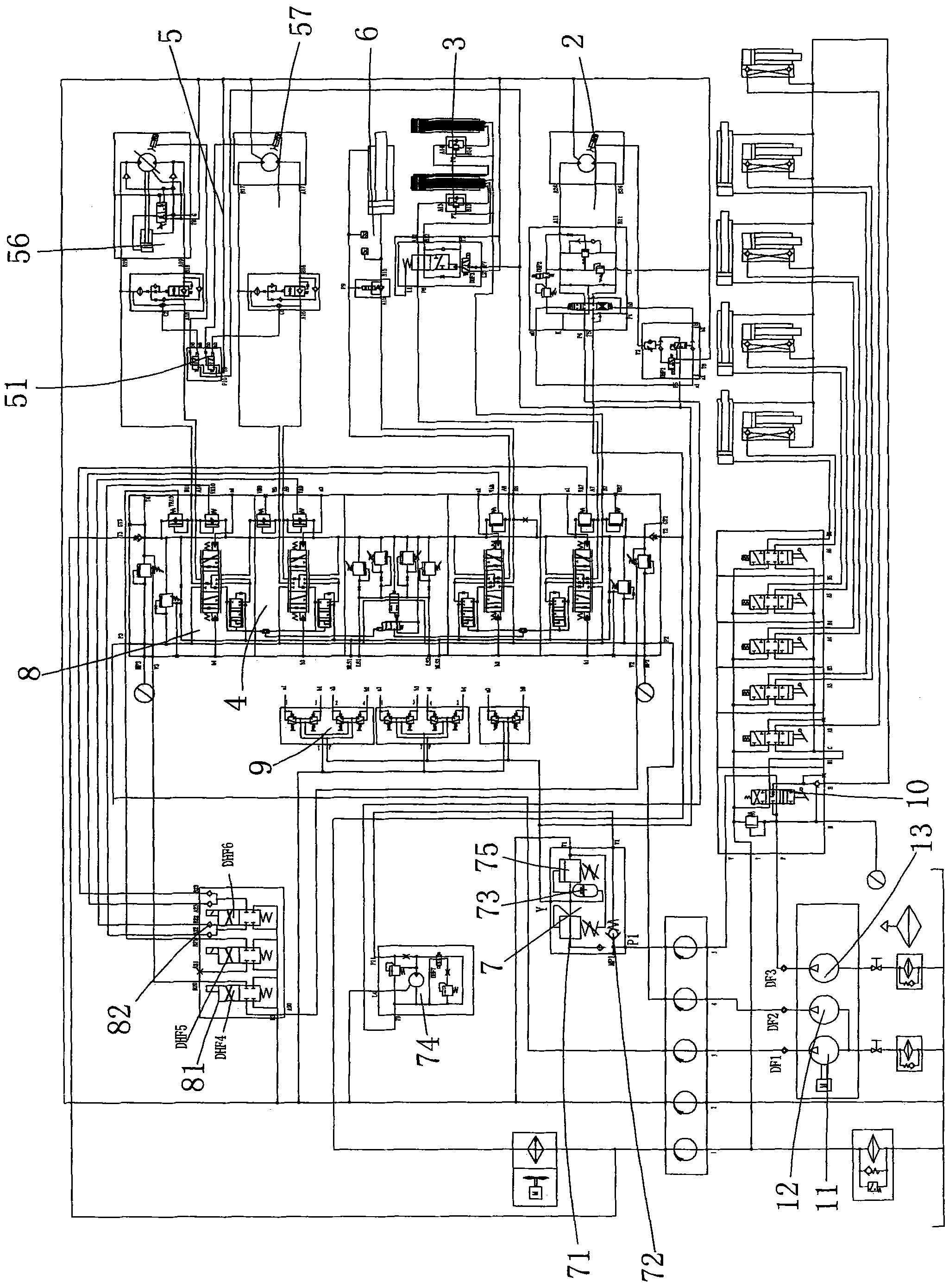
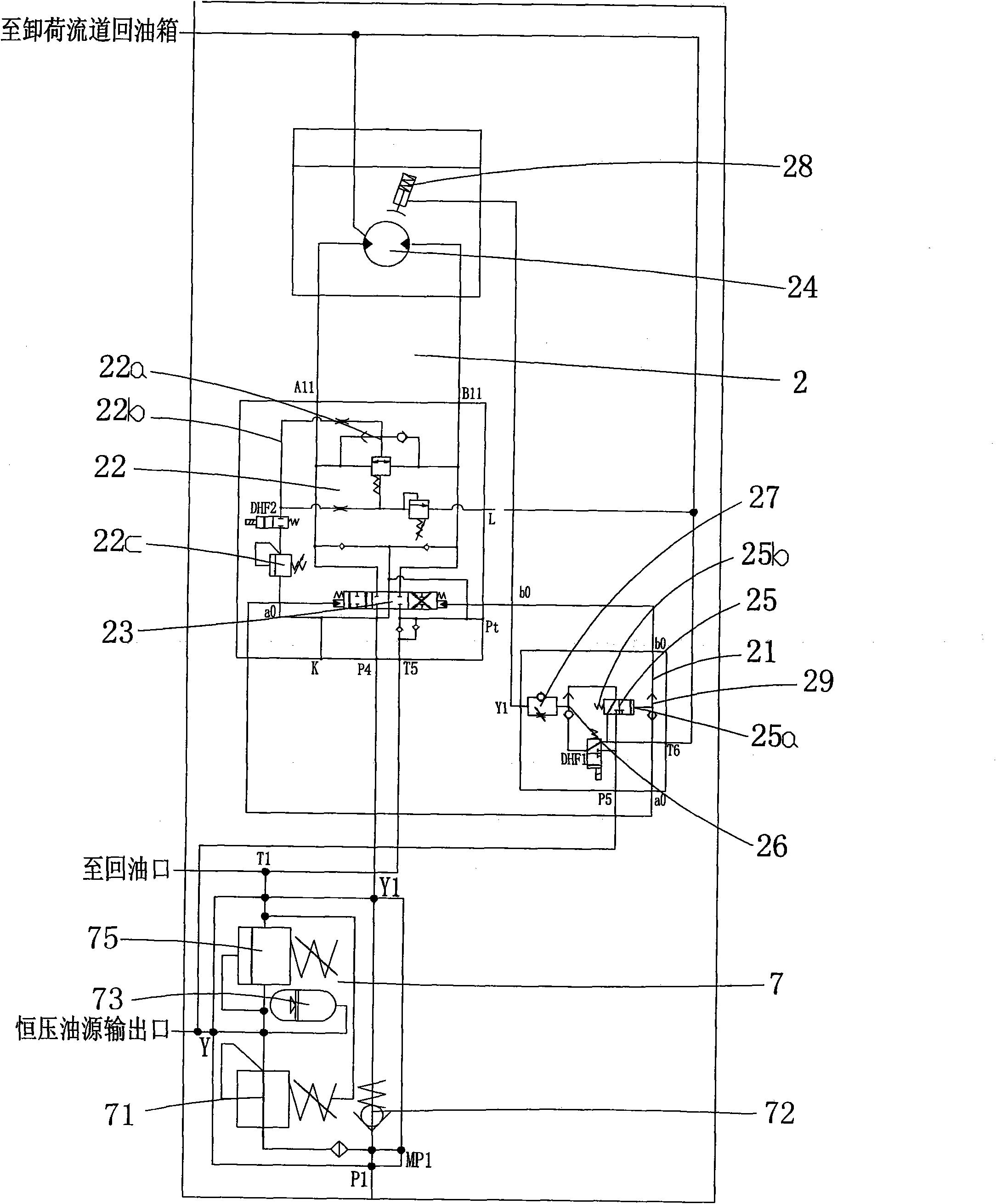
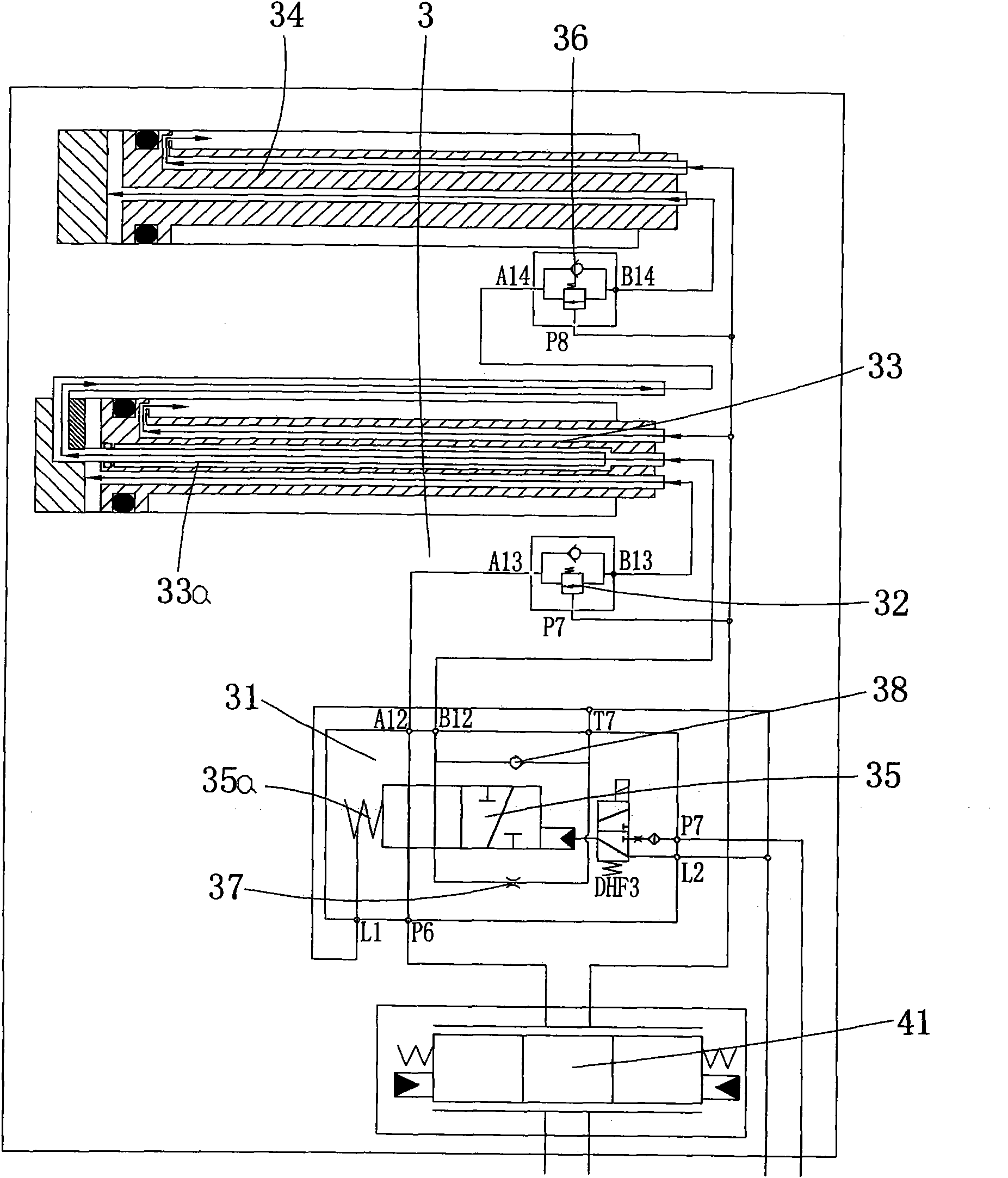
[0028] Such as Figure 1 to Figure 7 As shown, the symbol numbers are explained as follows: first oil pump 11, second oil pump 12, third oil pump 13, swing hydraulic system 2, swing brake control valve group 21, swing buffer valve group 22, first shuttle valve 22a, intermediate circuit 22b , the second pressure reducing valve 22c, the first reversing valve stem 23, the rotary motor 24, the first hydraulic control reversing valve 25, the driving end 25a, the spring chamber 25b, the second shuttle valve 26, the first one-way throttle valve 27. Swing brake 28, first control shuttle valve 29, boom telescopic hydraulic system 3, telescopic oil cylinder switching valve group 31, first one-way balance valve 32, first telescopic oil cylinder 33, transition sleeve 33a, second telescopic oil cylinder 34, the second hydraulic control reversing valve 35,...


PUM


Abstract

The invention relates to a hydraulic operation triple pump hydraulic system, which comprises a first oil pump, a second oil pump, a third oil pump, a rotary hydraulic system, a hoisting arm extension and retraction system, a safety unload hydraulic system, a lifting hydraulic system, a hoisting arm amplitude variation hydraulic system, a pressure reduction pilot oil source valve group and a control valve group, wherein the starting and closing characteristics of a rotary braking device, a main hoisting braking device and a sub hoisting braking device adopt the constant-pressure oil source control mode without additional external force operation, and the control on the braking devices can be intelligently and automatically realized according to the operation of each action. The invention realizes the fast-opening slow-closing control mode on a rotary structure and the slow-opening fast-closing control mode on main and sub hosting mechanisms according to different starting and closing characteristics of each mechanism, and effectively eliminates the pressure impact on the system. A flow distribution valve adopts the flow distribution mode irrelevant with a load, so slow action or noaction of executing mechanisms with high load pressure caused by pressure interference among all executing mechanisms can be effectively prevented. Each element in the whole vehicle system has high integration and modularization, and the maintenance is convenient.

Description

technical field [0001] The invention relates to the technical field of hydraulic systems, in particular to a hydraulically operated triple-pump hydraulic system, which is suitable for on-board use of truck cranes, crawler cranes and truck-mounted cranes. Background technique [0002] During the working process of the crane, it is necessary to frequently complete the actions of lifting with load, slewing with load, lowering of heavy objects, luffing and return without load. In order to achieve efficient work, the crane needs to be able to perform compound actions, that is, the above two or more simultaneous Action, with the continuous development and progress of crane technology, the requirements for the safety control of each actuator, the opening and closing characteristics of each actuator and the high integration of the hydraulic system components of the vehicle are also getting higher and higher. [0003] At present, the hydraulic system with many cranes adopts a multi-a...

Claims


Application Information

Patent Timeline
Patent Type & Authority Applications(China)
IPC IPC(8): B66C13/20
Inventor 卢宇李新邹泉敏刘峰刘富良
Owner 卢宇
Why Eureka
Try Eureka