Turbocharging system

A turbocharging system and turbine technology, applied in engine components, machines/engines, mechanical equipment, etc., can solve problems such as affecting engine air intake, complex testing, and disordered layout, and achieve shortened development cycles, accurate and fast response, and design. simple effect

Inactive Publication Date: 2013-12-18
ZHEJIANG GEELY AUTOMOBILE RES INST CO LTD +1
View PDF7 Cites 1 Cited by
  • Summary
  • Abstract
  • Description
  • Claims
  • Application Information

AI Technical Summary

Problems solved by technology

[0004] To sum up, it can be seen that when the traditional turbocharging system is cold started or the engine is at low speed, due to the small exhaust volume, the response of the turbine is poor, which affects the intake of the engine; at the same time, the compressor is prone to surge and blockage, which affects the compressor. The design and selection of the blades of the impeller and turbine have high requirements, and the matching of the turbine is difficult and the test is complica

Method used


Image

  • Turbocharging system
  • Turbocharging system

Examples


Example Embodiment

[0017] The present invention will be further described below with reference to the embodiments shown in the accompanying drawings.

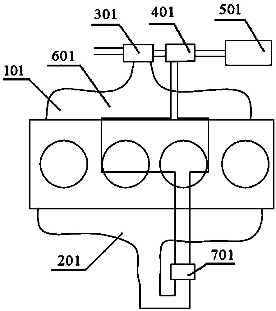
[0018] The traditional engine turbocharging system installs a turbine on the exhaust side, which uses the energy of the exhaust gas to drive the compressor to inhale fresh air, which saves energy and increases the intake power of the engine. like figure 1 Shown is a schematic structural diagram of a conventional engine turbocharging system, from which it can be seen that the system includes a turbine 301 connected to the exhaust manifold 101, a compressor 401 connected to the turbine 301, and an air filter 501 connected to the compressor 401 and The intercooler 601 ; wherein, the outlet of the air cleaner 501 is connected to the compressor 401 , and the other end of the intercooler 601 is connected to the throttle valve 701 . During operation, the intake air passes through the air cleaner 501 , the compressor 401 , and the intercooler 601 in seq...


PUM


Abstract

The invention discloses a turbocharging system and belongs to the technical field of an automobile engine. The turbocharging system comprises a turbine, an air filter, an air compressor, an intercooler, a generator and an electric motor, wherein the turbine is connected with an exhaust manifold; the generator is connected with the turbine; an outlet of the air filter is connected with an inlet of the air compressor; an outlet of the air compressor is connected with an inlet of the intercooler; an outlet of the intercooler is connected to a throttle valve of the engine; and moreover, the air compressor is also connected with the electric motor. According to the invention, the turbocharging system does not need to depend on air displacement; the air compressor is directly driven by the electric motor; the electric motor is controlled by an ECU (Electronic Control Unit) and is accurate and rapid to respond; surging and blockage of the air compressor do not need to be considered and blade design of the turbine is very simple; the air filter and the air compressor are arranged at the air inlet side nearby, so that an air inlet pipeline is greatly shortened; and a waste gate and a pressure protection valve are not required, the turbocharging system has a simple structure and is easy to match and the development period of the engine is greatly shortened.

Description

technical field [0001] The invention belongs to the technical field of automobile engines and relates to a turbocharging system. Background technique [0002] With the implementation of various energy-saving and environmental protection regulations, the application of turbocharging technology is becoming more and more extensive. Such as figure 1 Shown is a schematic structural diagram of a traditional turbocharging system, which includes a turbine 301 connected to the exhaust manifold 101, a compressor 401 connected to the turbine 301, an air filter 501 connected to the compressor 401 and an intercooler 601; wherein, the outlet of the air filter 501 is connected to the compressor 401, and the other end of the intercooler 601 is connected to the throttle valve 701. [0003] During operation, the turbine 301 drives the blades of the compressor 401 through the intermediate shaft, fresh air is compressed from the air filter 501 through the compressor 401 , cooled by the interc...

Claims


Application Information

Patent Timeline
IPC IPC(8): F01D15/10F02B39/10
Inventor 马茂康世邦刘岩沈源由毅冯擎峰
Owner ZHEJIANG GEELY AUTOMOBILE RES INST CO LTD
Why Eureka
Try Eureka