
High-integration hydraulic power device

A technology that integrates hydraulics and power devices. It is used in fluid pressure actuation devices, fluid pressure actuation system components, and mechanical equipment. It can solve problems such as unreasonable space layout, complicated pipelines, and low reliability, and achieve cooling effects. Good, low coefficient of friction, improved reliability

Pending Publication Date: 2019-02-15
JIANGSU JINLING INST OF INTELLIGENT MFG CO LTD +1
View PDF0 Cites 1 Cited by
  • Summary
  • Abstract
  • Description
  • Claims
  • Application Information

AI Technical Summary

Problems solved by technology

[0003] The traditional hydraulic power unit has heavy weight, complex piping, unreasonable space layout and low reliability

Method used


Image

  • High-integration hydraulic power device
  • High-integration hydraulic power device
  • High-integration hydraulic power device

Examples


Embodiment

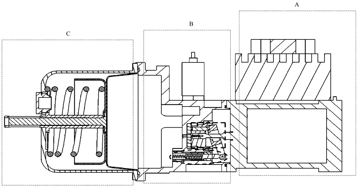
[0032] combine figure 1 , a highly integrated hydraulic power pack device, which is composed of motor system A, pump manifold B, fuel tank C, and three major parts. The pump manifold B is in the middle position, and the left and right sides are respectively connected to the fuel tank C and the motor system A by screws. .

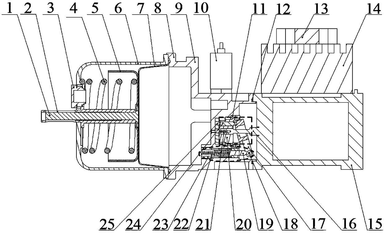
[0033] combine figure 2 , the motor system A includes motor 15, driver 14, cooling fan 13 three parts, motor 15 adopts the mode of horizontal installation, and utilizes screw to fix driver 14 and cooling fan 13 on the top of the motor in sequence; Oil motor, able to bear the pressure of oil. The driver 14 is installed above the motor to control the start and stop of the motor, and the top of the driver 14 is designed as a heat dissipation rib structure. Cooling fans 13 are installed above the driver for cooling.

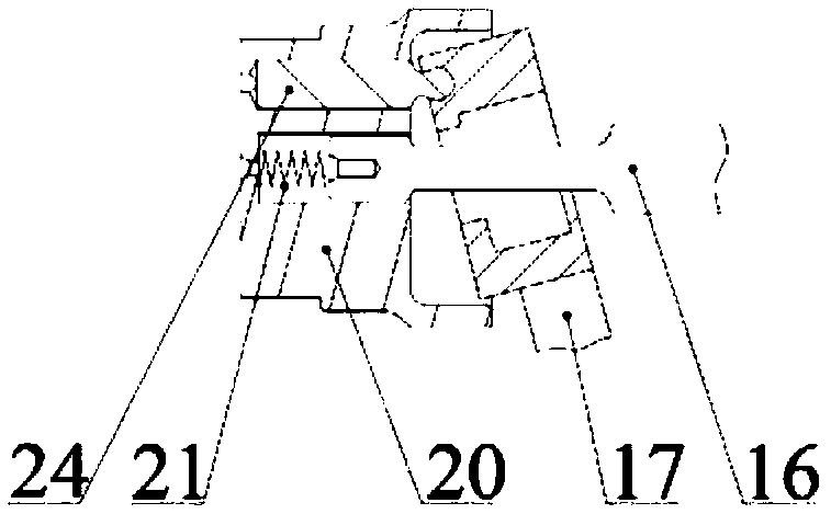
[0034] The pump manifold B is embedded with a constant pressure variable plunger pump, such as image 3 As shown, the plunger pump includes ...


PUM


Abstract

The invention discloses a high-integration hydraulic power device composed of three parts, namely, a motor system, a pump integrated block and an oil tank. The motor system comprises a motor, a driverand a cooling fan. A constant-pressure variable-displacement plunger pump is embedded in the pump integrated block. Accessories such as a sensor are installed on a shell of the constant-pressure variable-displacement plunger pump. The oil tank is composed of a push rod, a spring, a piston and a membrane. The motor and the plunger pump share one main shaft. A motor main shaft directly drags and rotates a plunger pump rotor to complete the oil suction and oil discharge process of the plunger pump, flow of oil is regulated through a piston drawing type variable-displacement mechanism, and therefore the function of constant pressure and variable displacement can be achieved. The high-integration hydraulic power device is used as a power conversion device of an airplane and has the beneficialeffects of being simple in structure, small in weight, easy to control, high in system efficiency and convenient to maintain.

Description

technical field [0001] The invention relates to a hydraulic power device, in particular to a highly integrated hydraulic power device. Background technique [0002] The hydraulic power unit can convert the mechanical energy of the motor into high-pressure hydraulic energy, so it is widely used in some actuators of aircraft. [0003] The traditional hydraulic power unit has heavy weight, complex piping, unreasonable space layout and low reliability. Contents of the invention [0004] The purpose of the present invention is to provide a highly integrated hydraulic power device with simple structure, light weight, easy control, high system efficiency and convenient maintenance. [0005] The technical solution for realizing the object of the present invention is: a highly integrated hydraulic power device, which is composed of a motor system, a pump manifold, and a fuel tank. The pump manifold is in the middle, and the left and right sides are respectively connected to the fu...

Claims


Application Information

Patent Timeline
Patent Type & Authority Applications(China)
IPC IPC(8): F15B21/08F15B21/0423
CPCF15B21/042F15B21/08
Inventor 郭登飞黄伟陈俊远沈小文蒋光超
Owner JIANGSU JINLING INST OF INTELLIGENT MFG CO LTD
Learn More