Buoy type dirt-blocking float-guiding device

A buoy-type and buoy technology, which is applied in the field of sewage blocking and drift-guiding devices for water intake holes in water conservancy and hydropower projects, can solve problems such as easy breaking, and achieve the effects of long service life, reliable connection and excellent working performance.

Active Publication Date: 2010-10-20
SICHUAN ORIENT HYDROELECTRIC ENG
View PDF1 Cites 8 Cited by
  • Summary
  • Abstract
  • Description
  • Claims
  • Application Information

AI Technical Summary

Problems solved by technology

[0006] In order to solve the above technical problems, the present invention proposes a method that can block the floating dirt before it accumulates in large quantities, and then guide it to the remote end of the working face of the non-hydraulic generator set or drainage pumping station, so as to ensure the normal operation of the unit. The running buoy type pollution control and drift guide device adopts this device, the connection between the buoy components is very firm, and it is not easy to be corroded and broken, and the relative rotation between the buoy and the anchor foundation on the shore can be generated in the horizontal and vertical directions, completely avoiding The problem that the connection between the buoy and the anchorage foundation is easily broken due to strong torsion is avoided, thus ensuring the service life of the pollution blocking and drifting device

Method used


Image

  • Buoy type dirt-blocking float-guiding device
  • Buoy type dirt-blocking float-guiding device
  • Buoy type dirt-blocking float-guiding device

Examples


Embodiment 1

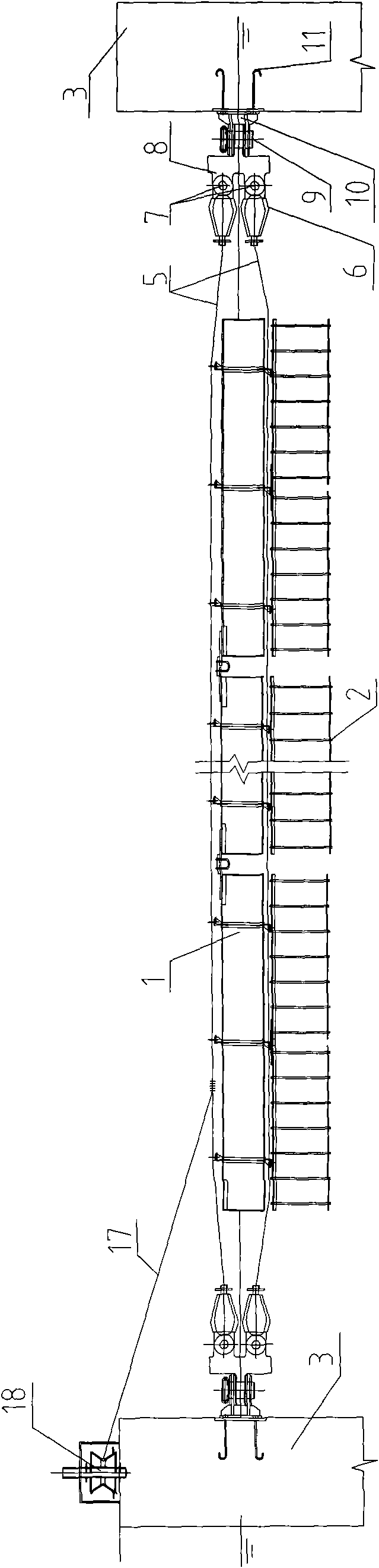
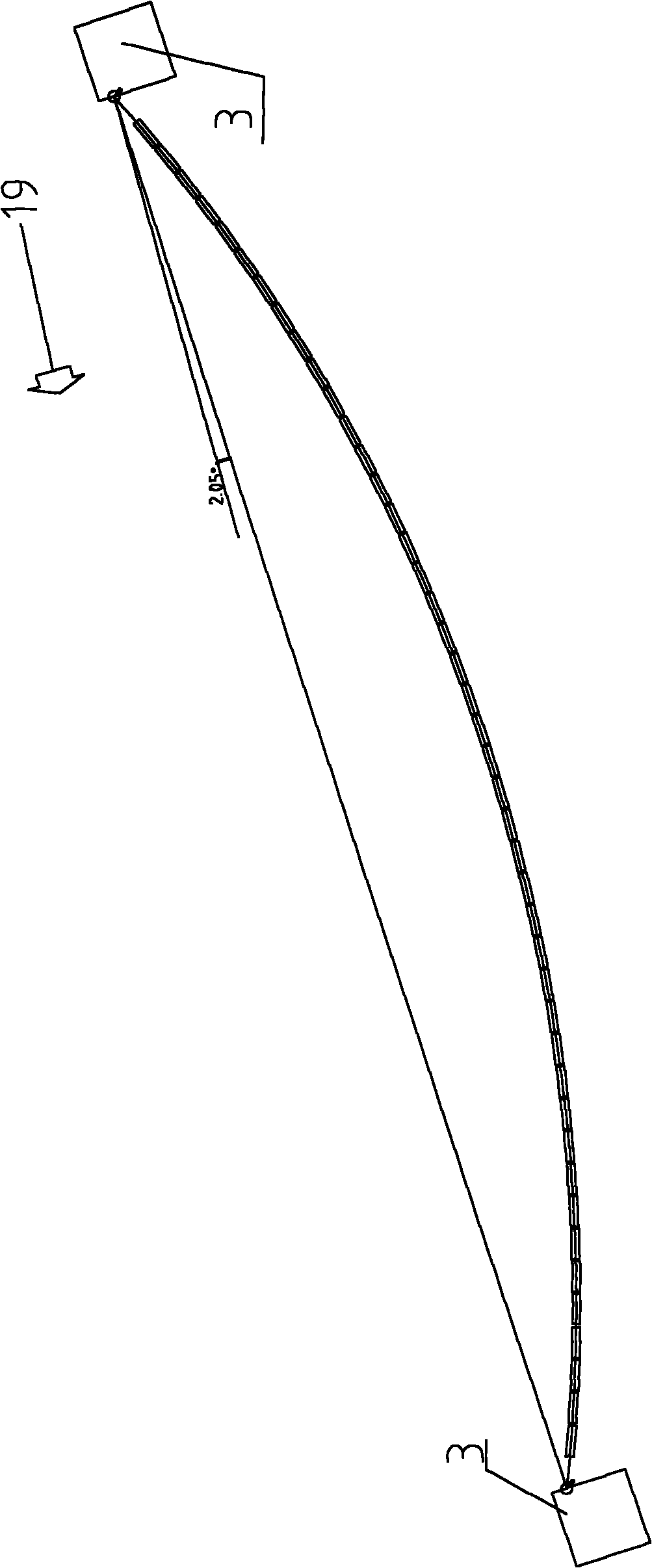
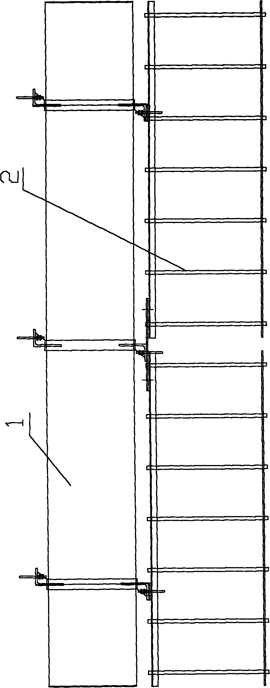
[0039] Refer to the attached Figure 1-5 , the present invention includes a buoy assembly 1, a hanging grid 2 arranged below the buoy assembly 1, a plurality of buoy assemblies 1 are connected as a whole and connected with an anchor foundation 3 provided on a bank or a dam body, and the upper and lower parts of the buoy assembly 1 are respectively Hanging lugs 4 are set, and suspension cables 5 are set in the lifting lugs 4. The two ends of the suspension cables 5 are connected to the anchor foundation 3 through the end connection devices. on the water. The end connecting device may be a wheel carrier in the prior art.

Embodiment 2

[0041] Refer to the attached Figure 1-13 , the present invention includes a buoy assembly 1, a hanging grid 2 arranged below the buoy assembly 1, a plurality of buoy assemblies 1 are connected as a whole and connected with an anchor foundation 3 provided on a bank or a dam body, and the upper and lower parts of the buoy assembly 1 are respectively Hanging lugs 4 are set, and suspension cables 5 are set in the lifting lugs 4. The two ends of the suspension cables 5 are connected to the anchor foundation 3 through the end connection devices. on the water. The end connection device includes a tapered sleeve 6 fixedly connected with the suspension cable 5, a cross hinge rod 8 connected with the tapered sleeve 6 through the first hinge shaft 7, and a cross hinge rod 8 connected with the cross hinge rod 8 through the second hinge The hinge base 10 connected with the shaft 9, and the embedded anchor 11 fixedly connected with the hinge base 10, the embedded anchor 11 is embedded in ...

Embodiment 3

[0043] On the basis of Embodiment 2, the first hinge axis 7 is arranged in a horizontal direction, and the second hinge axis 9 is arranged in a vertical direction.


PUM


Abstract

The invention discloses a buoy type dirt-blocking float-guiding device which relates to the technical field of related devices for water conservation and hydroelectric power. The buoy type dirt-blocking float-guiding device comprises a buoy subassembly and a hanging grid, wherein the hanging grid is arranged under the buoy subassembly, and a plurality of buoy subassemblies are connected into a whole and are connected with an anchoring base arranged on a bank or a dam body. The buoy type dirt-blocking float-guiding device is characterized in that the upper part and the lower part of the buoy subassembly are respectively provided with lifting lugs, a span wire is arranged in each lifting lug, both ends of the lifting lug are connected with the anchoring base by an end connection device, and the buoy subassembly is hung on a water surface at the front end of a water taking hole of a water-turbine generator set by the span wire. Due to the adoption of the device, the connection of the buoy subassemblies is very firm and is not easy to erode and break, the relative rotation can be generated between the buoy and the bank anchoring base in horizontal and vertical directions, and the problem that the connection between the buoy and the bank anchoring base is easy to break due to strong torsion is thoroughly avoided, thereby ensuring the service life of the dirt-blocking float-guiding device.

Description

technical field [0001] The invention relates to the technical field of equipment related to water conservancy and hydropower, in particular to a pollution-stopping and drift-guiding device for water intake holes of water conservancy and hydropower projects. Background technique [0002] After water conservancy and hydropower projects store water in the reservoir area, there will be a lot of floating dirt such as tree branches and leaves, crop weeds, plastic foam, domestic garbage, etc., especially during the flood season. These floating dirt often accumulate on the water surface. When the water intake hole of the project passes through the water, the floating dirt will float to the water intake hole with the water flow, and directly enter the electromechanical equipment such as the hydroelectric generator set or the drainage pump station through the water intake hole. If the amount of dirt is large enough, the size is large enough, and the texture is hard enough, it will def...

Claims


Application Information

Patent Timeline
Patent Type & Authority Applications(China)
IPC IPC(8): E02B5/08
Inventor 陈启春冷伟李邦宏
Owner SICHUAN ORIENT HYDROELECTRIC ENG
Why Eureka
Try Eureka