Partial emission pump with low specific speed

A technology of low specific speed and throat, applied in the direction of pumps, pump components, non-variable pumps, etc., can solve the problems of shortening the axial size, reducing the radial size of the impeller, and high efficiency, so as to suppress the axial vortex, Effect of reducing axial size and suppressing secondary flow

Active Publication Date: 2010-10-20
NO 11 INST OF NO 6 ACADEMY OF CHINA AEROSPACE SCI & TECH
View PDF4 Cites 10 Cited by
  • Summary
  • Abstract
  • Description
  • Claims
  • Application Information

AI Technical Summary

Problems solved by technology

[0004] The purpose of the present invention is to provide a new type of low specific speed partial flow pump, which solves the above-mentioned shortcomings of the existing low specific speed centrifugal pump, can reduce the radial size of the impeller, and because the impeller does not have front and rear cover plates, therefore There is no disk friction loss, so its efficiency is higher than that of conventional centrifugal pumps in the low specific speed range; because the partial flow pump has no gap characteristics, the impeller does not need front and rear sealing rings, thereby shortening the axial dimension; in addition, because the impeller of the partial flow pump It is an open structure, no axial force will be generated during operation, which reduces the difficulty of balancing the axial force of the turbo pump

Method used


Image

  • Partial emission pump with low specific speed
  • Partial emission pump with low specific speed
  • Partial emission pump with low specific speed

Examples


Embodiment Construction

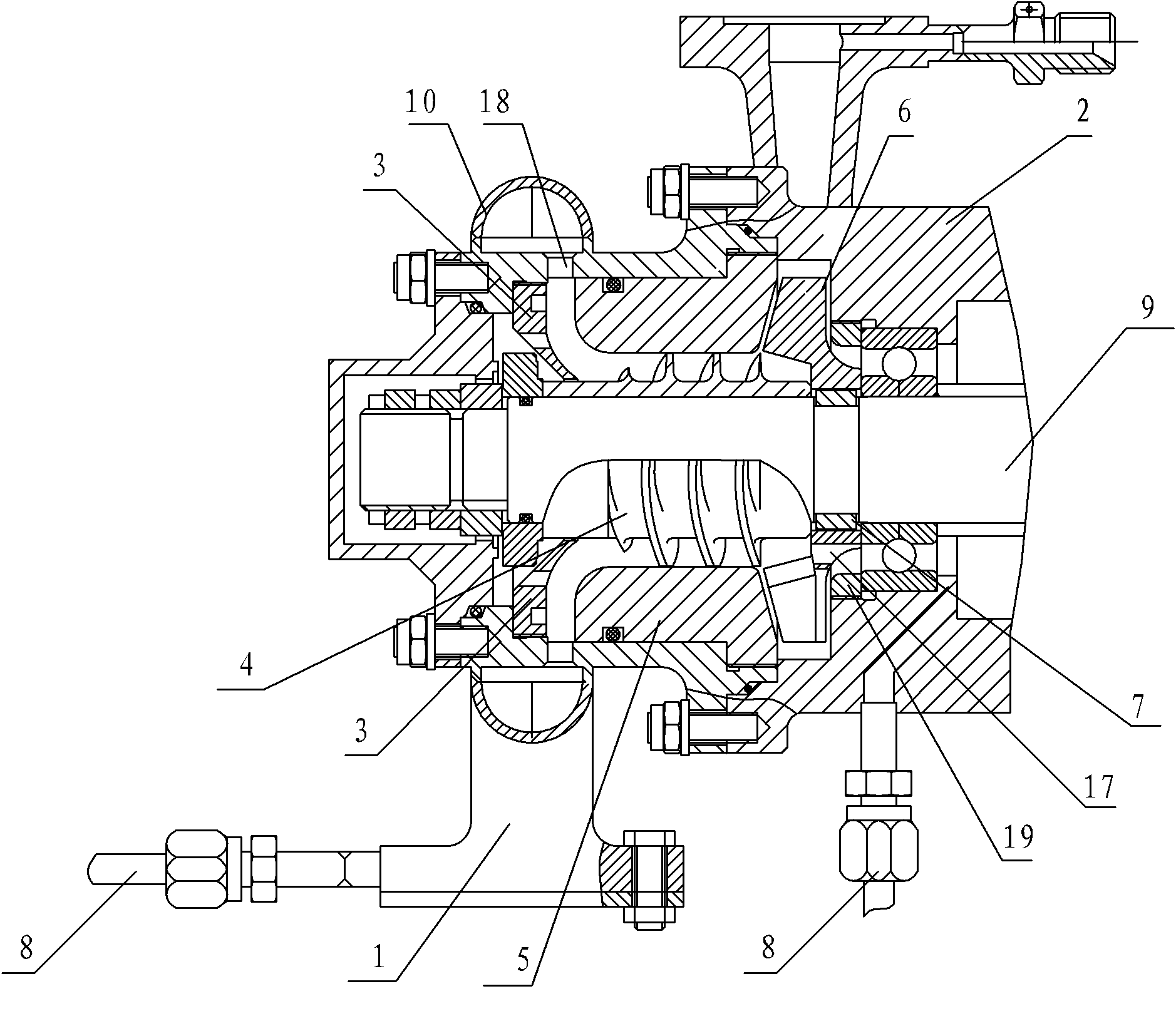
[0027] The low specific speed partial flow pump of the present invention, as figure 2 As shown, it includes an inlet assembly 1 and a housing assembly 2 .

[0028] Such as Figure 5 As shown, the inlet assembly 1 is composed of an inlet pipe 12 , a liquid collecting ring 10 and an inlet housing 11 . Due to the limitation of the overall structure of the turbine bias, the pump adopts a radial inlet, the liquid collecting ring 10 and the inlet pipe 12 are welded on the inlet casing, and a certain number of small radial holes 18 are designed on the inlet casing to ensure the collection The propellant in the liquid ring enters the pump evenly.

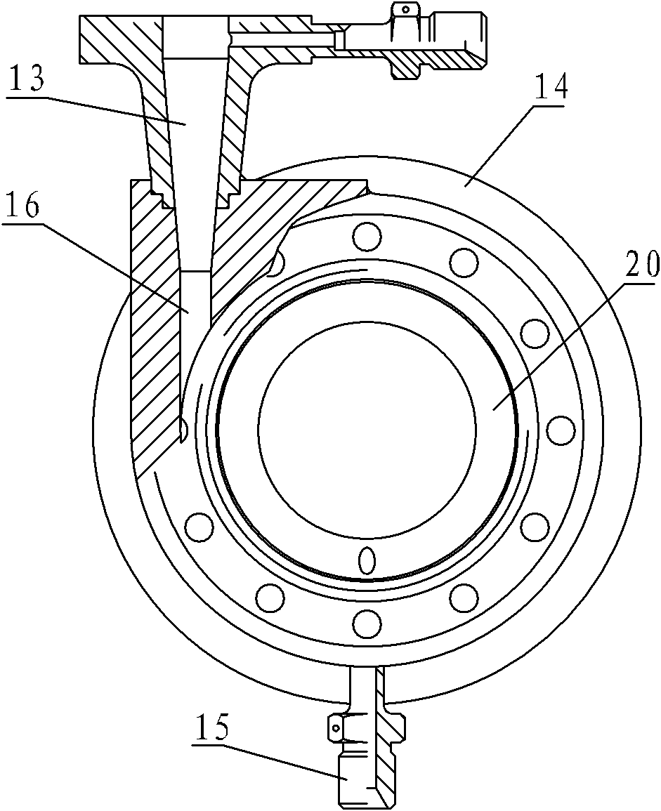
[0029] Such as figure 2 and image 3 As shown, the housing assembly includes a housing 14, a throat 16, a welding nozzle 15 and a diffuser pipe 13; the welding nozzle 15 is welded to the housing 14; the impeller 6, the induction wheel 4, the transmission shaft 9 and the guide sleeve 5 are set Inside the housing 14; the throat 16 is a...


PUM


Abstract

The invention relates to a partial emission pump with a low specific speed, which comprises an inlet component and a shell component. The shell component comprises a shell, an impeller, an inducer, a transmission shaft, a diversion sleeve and a diffusion pipe; the impeller, the inducer, the transmission shaft and the diversion sleeve are arranged in the shell; the diffusion pipe is arranged on the shell and is communicated with the shell; the inlet component comprises an inlet shell and an inlet pipe; the inlet pipe is connected with the inlet shell; the partial emission pump also comprises a throat part arranged on the shell; the shell is communicated with the diffusion pipe through the throat part; and the central line of the diffusion pipe is parallel to the external tangent line of an annular channel on the shell. The invention solves the technical problems of narrow blade outlet, difficult manufacture and processing of the impeller and low efficiency of the centrifugal pump, facilitates the large-scale adjustment of operating conditions, and improves the hydraulic efficiency of the pump.

Description

technical field [0001] The invention belongs to the field of turbo pumps, in particular to a low specific speed partial flow pump. Background technique [0002] In the field of turbo pumps, it is customary to use conventional centrifugal pumps to pressurize the propellant components to achieve the purpose of delivering high-pressure propellants. Existing low specific speed centrifugal pumps see figure 1 , which has the following defects: 1. The outer diameter of the impeller is too large, the width of the blade outlet is small, the flow channel on the axial surface of the impeller is narrow and long, and the diffusion of the flow channel is relatively serious. The reverse pressure gradient inside the flow channel will promote the development and separation of the wall boundary layer , the jet-wake structure is strengthened, the wake area is increased, and the hydraulic performance is reduced; 2. The mechanical loss is mainly the friction loss of the disc, which is proportio...

Claims


Application Information

Patent Timeline
Patent Type & Authority Applications(China)
IPC IPC(8): F04D29/44F04D29/22F04D29/24F04D29/66
Inventor 杜玉洁
Owner NO 11 INST OF NO 6 ACADEMY OF CHINA AEROSPACE SCI & TECH
Why Eureka
Try Eureka