
Coaxial cable for low frequency

A coaxial cable and low-frequency technology, applied in the field of coaxial cables, can solve problems such as not being able to effectively reflect the concise structure, and achieve the effects of reducing material consumption, saving resources, and facilitating on-site construction

Inactive Publication Date: 2010-10-20
CHANGSHU HONGLIN WIRE & CABLE CO LTD
View PDF8 Cites 0 Cited by
  • Summary
  • Abstract
  • Description
  • Claims
  • Application Information

AI Technical Summary

Problems solved by technology

The coaxial cable with this patented structure has not yet completely got rid of the design style of the coaxial cable used under high frequency conditions, so it is still not enough to effectively reflect the concise structure and resource saving, so there is still a need for improvement. The technology to be introduced below The scheme is based on this premise

Method used


Image

  • Coaxial cable for low frequency
  • Coaxial cable for low frequency
  • Coaxial cable for low frequency

Examples


Embodiment 1

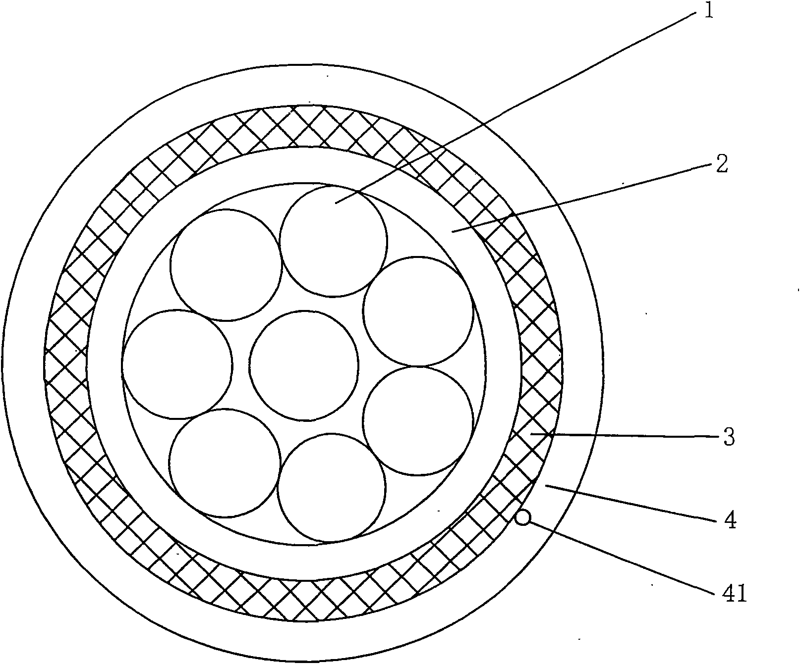
[0022] Please see figure 1 and figure 2 , see first figure 1 , a group of 8 cable cores 1 is given, and an aluminum composite tape overall shielding layer 2 is arranged outside a group of cable cores 1, and a braided overall shielding layer 3 is arranged outside the aluminum composite tape overall shielding layer 2. The braided overall shielding layer 3 is extruded and covered with a sheath layer 4 according to the usual method in the wire and cable industry, and the sheath layer 4 can also be called an outer sheath. In a preferred solution, a tear line 41 can also be designed on the sheath layer 4 to facilitate tearing during use.

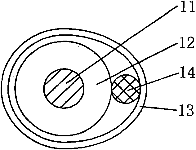
[0023] see details figure 2 ,exist figure 2 The specific structure of the aforementioned group of (8) cable cores 1 is shown in , since the structures of the 8 cable cores 1 are all the same, the applicant chooses figure 2 One of the illustrated cores 1 is detailed below. An insulating layer 12 is extruded outside a conductor 11 , and a ...

Embodiment 2

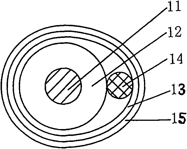
[0026] exist figure 2 The composite tape 13 of the cable core 1 of the structure shown is provided with a polyester tape layer 5 outside, and the polyester tape layer 5 can be omitted under normal circumstances, such as the structure of embodiment 1. All the other are the same as the description to embodiment 1.

[0027] As can be seen from Examples 1 and 2, the technical solution provided by the present invention saves one layer of composite tape (the prior art uses double-layer metal composite tape) and one layer located at the The outermost inner sheath of cable core 1. As a result, the overall diameter of the coaxial cable can be further reduced, which is not only beneficial to construction work, but also can save raw materials during manufacturing, so as to reflect the saving of resources. In particular, even if one layer of composite tape and inner sheath is omitted, it will not affect the performance in any way.


PUM

PropertyMeasurementUnit
Thicknessaaaaaaaaaa
Thicknessaaaaaaaaaa
Thicknessaaaaaaaaaa

Abstract

The invention relates to a coaxial cable for low frequency, belonging to the technical field of communication cables. The coaxial cable comprises a group of cable cores, a total shielding layer of an aluminum composite strip, a total weaving shielding layer and a sheath layer, wherein the total shielding layer of the aluminum composite strip is located outside the group of cable cores, the total weaving shielding layer is located outside the total shielding layer of the aluminum composite strip, and the sheath layer is located outside the total weaving shielding layer. The coaxial cable is characterized in that each of the cable cores comprises a conductor, an insulating layer, a composite strip and a ground wire, wherein the insulating layer is located outside the conductor, the composite strip is located outside the insulating layer, the ground wire is located between the insulating layer and the composite strip, and the composite strip is formed by a polyester strip and a metallic layer combined at the surface of one side of the polyester strip. The invention has the advantage of simplified structure, which ensures that the whole diameter of the formed coaxial cable is reduced, thereby facilitating site construction and being beneficial to reducing material consumption so as to save resources.

Description

technical field [0001] The invention belongs to the technical field of communication cables, and in particular relates to a low-frequency coaxial cable. Background technique [0002] A large number of technical solutions related to coaxial cables can be found in Chinese patent documents, such as CN1126193C discloses a high-frequency transmitting coaxial cable, CN201281983Y discloses an anti-interference coaxial cable, CN201274197Y introduces a high-frequency coaxial cable, and CN201298399Y recommends There is a coaxial cable with double-layer shielding and CN101635182A discloses a coaxial cable for high frequency and its manufacturing method, etc. [0003] The above-mentioned coaxial cables have good versatility. The so-called good versatility means that in addition to meeting the high-frequency conditions, they can be used under low-frequency conditions. Cables used in low-frequency conditions will undoubtedly cause waste of resources. Therefore, it is unreasonable to use...

Claims


Application Information

Patent Timeline
IPC IPC(8): H01B11/20
Inventor 颜君
Owner CHANGSHU HONGLIN WIRE & CABLE CO LTD
Learn More