Automatic compensating circuit for uncooled semiconductor laser wavelength temperature-following drift

An automatic compensation and laser technology, applied to semiconductor lasers, lasers, laser components, etc., can solve the problems of small number of channels, complexity, and low total transmission rate, so as to increase the number of channels and total transmission rate, reduce complexity and cost effect

Active Publication Date: 2010-10-20
HUAZHONG UNIV OF SCI & TECH
View PDF4 Cites 13 Cited by
  • Summary
  • Abstract
  • Description
  • Claims
  • Application Information

AI Technical Summary

Problems solved by technology

However, the wavelength of the semiconductor laser changes with temperature, and its value is about 0.1nm / °C. If the output wavelength of the Uncooled laser is required to be effective in the temperature range of -20°C to 60°C, since the range of single-channel wavelength can vary When it reaches nearly 8nm, the channel spacing of CWDM must be above 20nm, the number of available channels is very small, and the total transmission rate is not high
Therefore, a simple and effective compensation method to solve the wavelength drift with temperature is needed to solve the problem of excessive channel spacing and few total available channels
In recent years, foreign research institutions have studied this problem, and the methods they adopt can ensure that the wavelength of the Uncooled laser is basically unchanged in the range of 20°C to 70°C ["Uncooled DBR Laser Directly Modulated at 3.125Gb / s as Athermal Transmitter for Low-Cost WDM Systems", IEEE PHOTONICS TECHNOLOGY LETTERS, VOL.17, NO.10, OCTOBER 2005], but this method needs to add corresponding control circuit system to realize wavelength control, and it needs to measure temperature, which is still complicated , the production cost is relatively high

Method used


Image

  • Automatic compensating circuit for uncooled semiconductor laser wavelength temperature-following drift
  • Automatic compensating circuit for uncooled semiconductor laser wavelength temperature-following drift
  • Automatic compensating circuit for uncooled semiconductor laser wavelength temperature-following drift

Examples


Embodiment

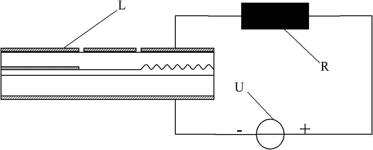
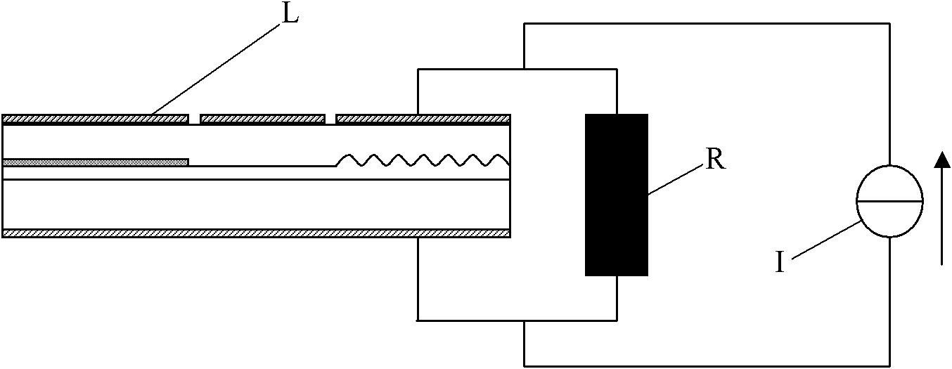
[0017] Here is a specific example of a constant voltage source driving a series circuit:

[0018] The relationship between the resistance value R of the thermistor and the temperature can be expressed as:

[0019] R=R 0 gexp(Bg(1 / (T+273)-1 / 293))+R C

[0020] In the above formula, T is the temperature in Celsius, R 0 is the resistance value of the thermistor at a temperature of 20°C. B is the material constant of the negative temperature coefficient (NTC) thermistor, also known as the thermal index, and the B value range is generally between 2000K and 6000K. R C Indicates a fixed-value resistor that can be connected in series according to actual needs. R can be determined by experiments and calculations 0 , B and R C , to meet the temperature compensation requirements.

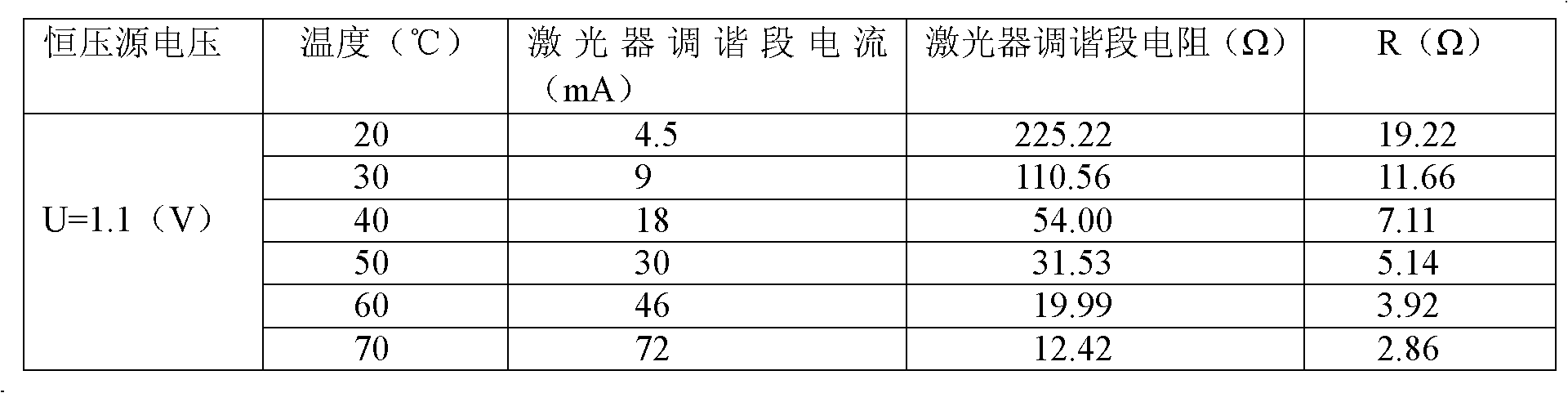
[0021] First of all, it is necessary to determine the R value corresponding to the wavelength temperature drift that can be compensated at different temperatures. The relevant data are as follows:

[...


PUM


Abstract

The invention provides an automatic compensating circuit for uncooled semiconductor laser wavelength temperature-following drift. The circuit comprises an uncooled semiconductor laser and a thermistor; the thermistor is connected with a tuning section of the uncooled semiconductor laser; and the circuit is driven by a constant voltage source or a constant current source. The circuit automatically compensates the uncooled semiconductor laser wavelength temperature-following drift for optical communication by adopting a simple and effective method. Compared with other technology aiming at the problem, the circuit does not need to add a control circuit system to adjust the wavelength, and does not need to measure the temperature of the laser so as to greatly reduce the complexity and cost of an uncooled optical transmitter module, meet the requirement of a CWDM for implementing a more economic and more practical optical network and increase the available channel number and total transmission rate of the CWDM network at the same time.

Description

technical field [0001] The invention relates to a new thermistor-based circuit for automatically compensating the wavelength drift of an uncooled (Uncooled) semiconductor laser used in optical communication with temperature. The invention can automatically compensate the temperature drift of the laser wavelength, and is very simple and practical. There is no need to add an external control circuit to adjust the wavelength, and it is not necessary to measure the temperature of the laser, which can greatly reduce the volume and cost of the optical transmitter. Background technique [0002] Sparse Wavelength Division Multiplexing (CWDM, Coarse Wavelength Division Multiplexing) is a more economical and practical solution to optical communication networks, which has received great attention in recent years. One of the main advantages of CWDM technology is that it uses Uncooled semiconductor lasers As an optical transmitter, the Uncooled semiconductor laser does not require thermo...

Claims


Application Information

Patent Timeline
Patent Type & Authority Applications(China)
IPC IPC(8): H01S5/068H01S5/024
Inventor 王皓余永林
Owner HUAZHONG UNIV OF SCI & TECH
Why Eureka
Try Eureka