
Eureka
For R&D, Eureka makes reading and utilizing patents & technical documents easy.
Eureka AIR
Designed for self-driven R&D workflows. Generate viable solutions, solve complex R&D challenges, empower your innovation with AI.

Eureka Materials
Designed for material experts only. Revolutionize your material R&D, from search, analyze, to developing new materials.

TechResearch
Generate reliable direction feasibility study reports for your R&D in just a few steps.

TechSeek
Discover and master advanced knowledge NOW. Basics, ideas, possibilities, all at once.

TechMind
As an expert in R&D Theories, TechMind can generates customized viable solutions instantly.

TechRisk
Analyze your overall solution with one click, know your potential R&D risks in advance.

TechMonitor
Get weekly tech updates, stay abreast of the latest tech innovations and key insights.
Magnetic engine
An engine and magnetic technology, applied in the direction of generators/motors, electrical components, etc., can solve the problems of serious pollution and high energy consumption, and achieve the effect of wide application, convenient installation and processing, and easy replacement.
- Summary
- Abstract
- Description
- Claims
- Application Information
AI Technical Summary
Problems solved by technology
Method used
Image

Examples
Embodiment 1
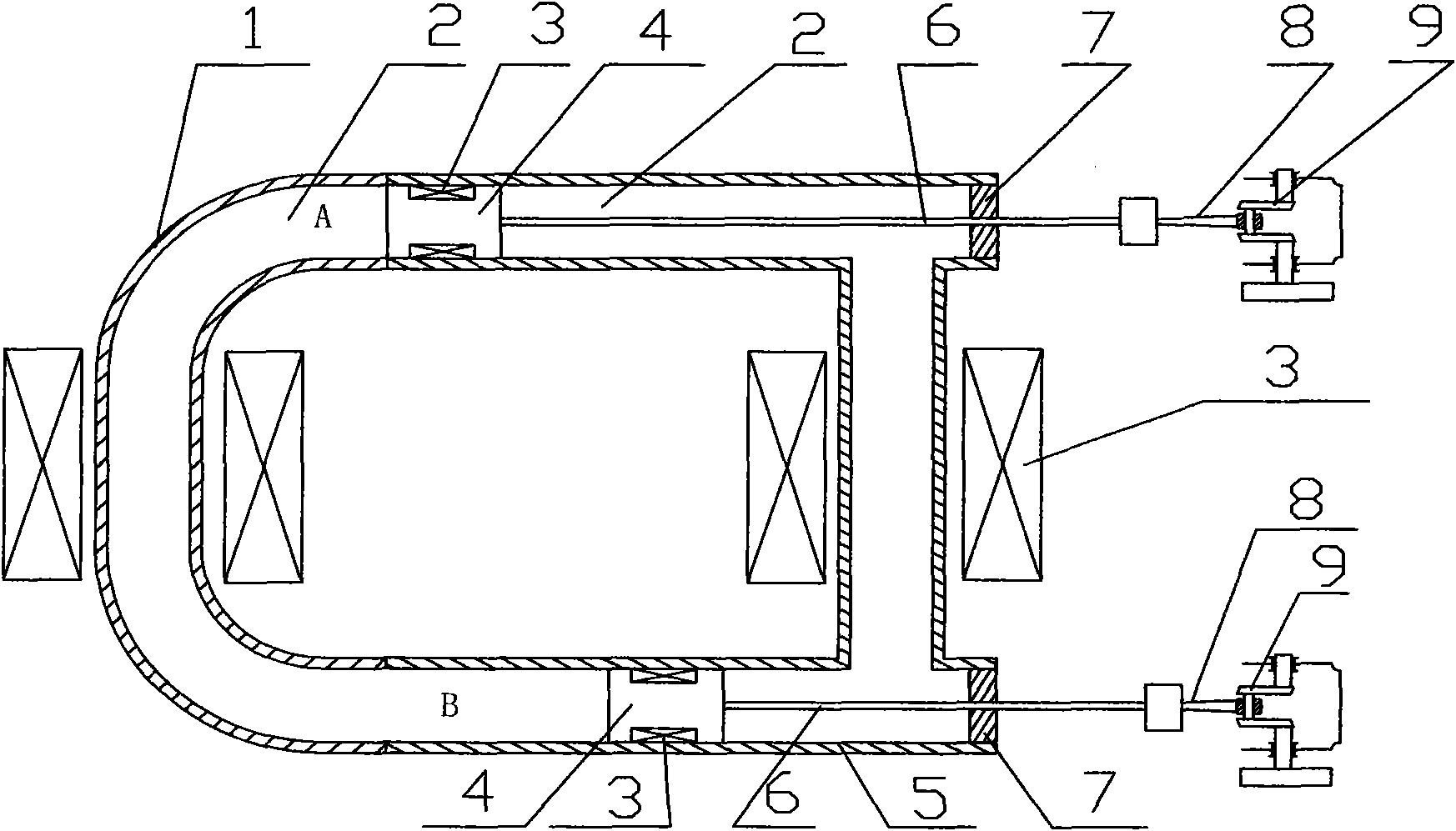
[0071] Embodiment 1: a kind of magnetic motor (referring to attached figure 1 ), including a U-shaped pipe 1, an I-shaped pipe 5, two pistons 4 and an output shaft 6 connected to the piston 4, two ports of the U-shaped pipe 1 are respectively connected with two ports on one side of the I-shaped pipe 5, and U The straight section in the middle of the tube 5 is wrapped with a coil 3 and the coil 3 is fixed; the straight section in the middle of the I-shaped tube 5 is wrapped with a coil 3 and fixed; the piston 4 is arranged between the I-shaped tube 5 and the U-shaped tube. The joint of the tube 1 is matched with the I-shaped tube 5, one end of the output shaft 6 is fixed in the middle of the corresponding end face of the piston 4, and the other end of the output shaft 6 passes through the through hole of the I-shaped tube 5 and is connected from the I-shaped tube 5. The other side protrudes from the port; the coil 3 is wrapped around the piston 4 with the moving direction of th...
Embodiment 2
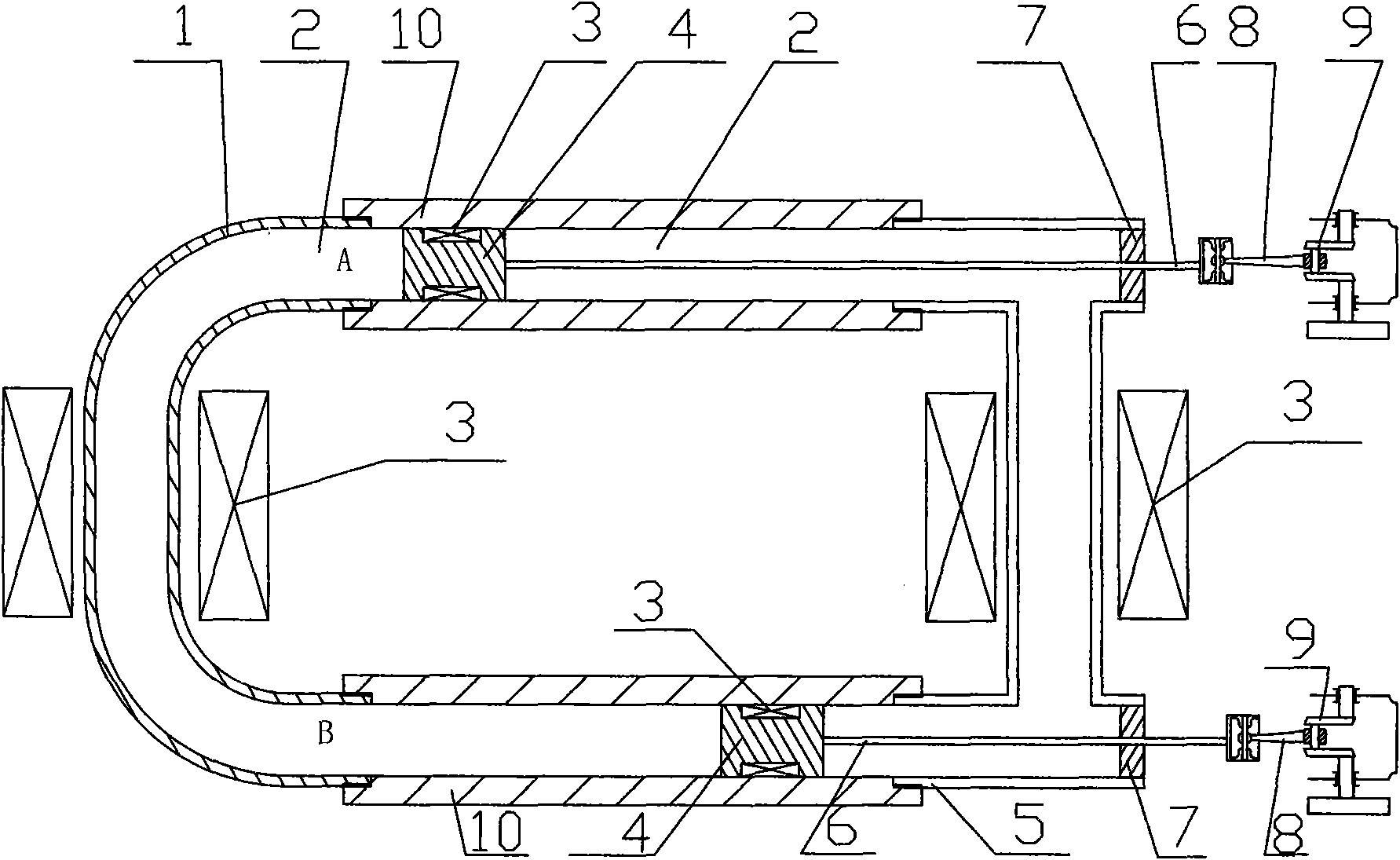
[0074] Embodiment 2: a kind of magnetic motor (referring to attached figure 2 ), its basic structure is the same as embodiment 1, and the difference is: the junction of U-shaped pipe 1 and I-shaped pipe 5 is provided with straight pipe 10, and the two ends of straight pipe 10 are connected with U-shaped pipe 1 and I-shaped pipe respectively. The type pipe 5 is threaded, the piston 4 is arranged in the straight pipe 10 and the piston 4 is matched with the straight pipe 10.
Embodiment 3
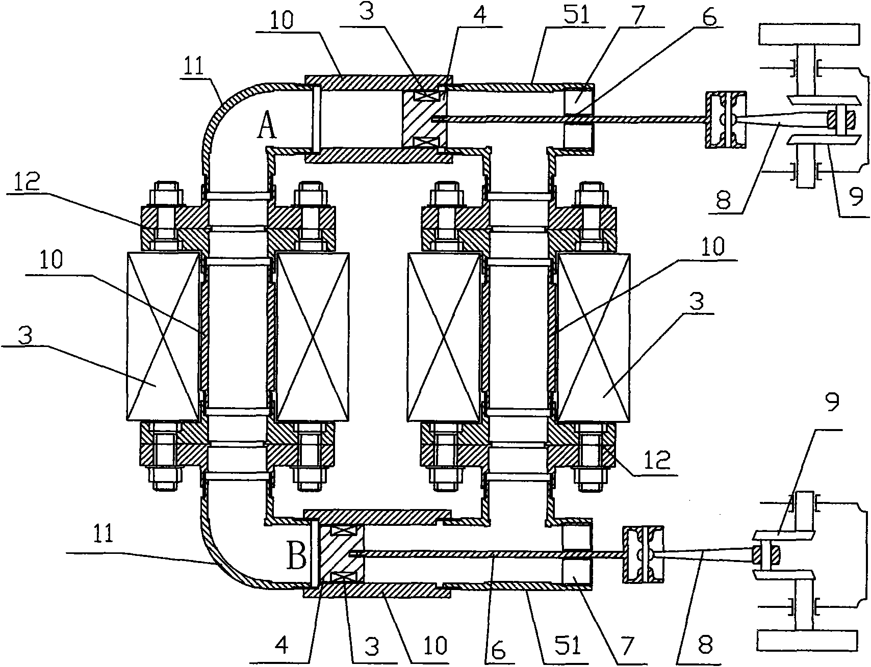
[0075] Embodiment 3: a kind of magnetic motor (referring to attached image 3 ), its basic structure is the same as that of Embodiment 2, and the difference is: U-shaped pipe 1 includes a straight pipe 10 and two 90-degree elbows 11, and the two ends of the straight pipe 10 are connected with the two 90-degree elbows 11 respectively. One end is threaded; the I-shaped pipe 5 includes two 90-degree tees 51 and a straight pipe 10, and the two ends of the straight pipe 10 are respectively threaded with one end of the two 90-degree tees 51; the U-shaped pipe 1 and the I-shaped Type pipe 5 all adopts combined structure. Flanges 12 are provided at the joints between the straight pipe 10 of the U-shaped pipe 1 and the two 90-degree elbows 11 of the U-shaped pipe 1, and the coil 3 outside the straight section of the U-shaped pipe 1 is fixed on the straight pipe through the flange 12. Tube 10 outside. A flange 12 is provided at the connection between the straight pipe 10 of the I-shap...
PUM
 Abstract
Description
Claims
Application Information
 - R&D Engineer
- R&D Manager
- IP Professional
- Industry Leading Data Capabilities
- Powerful AI technology
- Patent DNA Extraction
Browse by: Latest US Patents, China's latest patents, Technical Efficacy Thesaurus, Application Domain, Technology Topic, Popular Technical Reports.
© 2024 PatSnap. All rights reserved.Legal|Privacy policy|Modern Slavery Act Transparency Statement|Sitemap|About US| Contact US: help@patsnap.com