
Floating oil return mechanism

A technology of oil return pipe and oil return flange, which is applied in the field of floating oil return mechanism, can solve the problems of poor oil return, flattened hose, and affecting lubrication effect, etc., and achieves the effect of convenient maintenance and strong adaptability

Active Publication Date: 2010-10-27
CHINA NAT HEAVY MACHINERY RES INSTCO
View PDF4 Cites 2 Cited by
  • Summary
  • Abstract
  • Description
  • Claims
  • Application Information

AI Technical Summary

Problems solved by technology

The field practice shows that when the hose connection is used, the hose is often folded and flat, resulting in serious oil return and affecting the lubrication effect, and sometimes the hose is broken and oil leakage occurs, causing pollution and waste

Method used


Image

  • Floating oil return mechanism
  • Floating oil return mechanism

Examples


Embodiment Construction

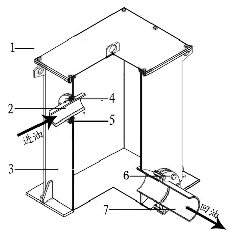
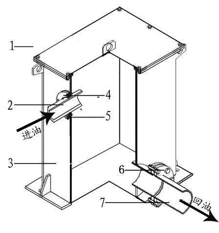
[0011] Such as figure 1 As shown, it includes a sealing box body 3, a box cover 1, an oil inlet flange 4, a rubber gasket 5, an oil inlet pipe 2, an oil return flange 6 and an oil return pipe 7. The sealing box body 3 is a welded structural part fixed on On the basis; the tank cover 1 is a welded cover plate with a handle for easy cleaning and installation adjustment; the oil inlet flange 4 is fixed on the upper side of the sealed box body 3 to guide the oil inlet pipe 2; the oil inlet pipe 2 and The body of the uncoiler is rigidly connected, and rubber gaskets 5 are installed between the oil inlet flanges 4 to prevent external debris from contaminating the lubricating oil and oil leakage; the oil return flange 6 is fixed directly below the sealing box 3, and the oil return flange 6 Connect the oil return pipe 7 to ensure that the oil return pipe 7 is unimpeded, and the oil return pipe 7 is connected to the oil tank of the thin oil lubrication station through the intermediate ...


PUM


Abstract

The invention relates to the field of metallurgical equipment, in particular to a floating oil return mechanism in a floating decoiler. The mechanism is characterized by at least comprising a sealing box body, a box cover, an oil inlet flange, a rubber sealing gasket, an oil inlet pipe, an oil return flange and an oil return pipe, wherein the oil return pipe is connected with an oil box of a thin oil lubrication station through an intermediate piping; the sealing box body is a welding structural member and fixed on a foundation; the oil inlet flange is fixed on the upper side part of the sealing box body; the oil inlet pipe is in rigid connection with the decoiler body; the oil return flange is fixed right below the sealing box body and connected with the oil return pipe; and the oil inlet pipe floats and stretches in the sealing box body through the guide of the oil inlet flange and the sealing of the rubber sealing gasket in the presence of the drive of the floating decoiler body to ensure that lubricating oil flows in the sealing box body and then flows back to the thin oil lubrication station through the oil return pipe at the bottom of the sealing box body. The floating oil return mechanism has simple structure, guarantees smooth oil return and is completely suitable for the floating oil return working conditions of the floating decoiler.

Description

technical field [0001] The invention relates to the field of metallurgical equipment, in particular to a floating oil return mechanism in a floating uncoiler of cold rolling, levelling, pickling, cleaning, tension leveling and shearing units. Background technique [0002] Among the floating uncoilers of cold rolling, tempering, pickling, cleaning, tension leveling and shearing units, most of the floating uncoilers are lubricated with thin oil circulation. In order to ensure that the strip center is always kept on the center line of the unit, the uncoiler has a The CPC automatic centering device, that is, the uncoiler body device floats in real time, and the lubricating oil return pipeline is generally directly connected with a hose to compensate for the floating amount of the uncoiler. Field practice shows that when hose connections are used, the hoses are often folded and flattened, resulting in serious oil return and affecting the lubrication effect, and sometimes the hose...

Claims


Application Information

Patent Timeline
IPC IPC(8): B21C47/16
Inventor 计江
Owner CHINA NAT HEAVY MACHINERY RES INSTCO
Learn More