
Material diversion mechanism

A technology of shunt mechanism and materials, applied in the direction of conveyor objects, transportation and packaging, packaging, etc., can solve the problems of increased cylinder cost, low work efficiency, material wear, etc., to achieve high efficiency and improve efficiency.

Inactive Publication Date: 2010-10-27
江阴纳尔捷机器人有限公司
View PDF5 Cites 46 Cited by
  • Summary
  • Abstract
  • Description
  • Claims
  • Application Information

AI Technical Summary

Problems solved by technology

[0003] 1. As the width of the material conveying line changes, the stroke of the cylinder must change accordingly to push the material to the branch conveying line, resulting in an increase in the cost of the cylinder
[0004] 2. One material is pushed to the branch conveying line by the cylinder. After the cylinder retracts to the initial position, the next material can continue to be conveyed to the pushing position of the cylinder, and then the material is pushed to the branch conveying line. Therefore, if the cylinder stroke is long, It will take a long time for the cylinder to go back and forth, resulting in low work efficiency
[0005] 3. When the material is pushed by the cylinder, there is sliding friction between the material and the conveying line, which will wear the material to a certain extent

Method used


Image

  • Material diversion mechanism
  • Material diversion mechanism
  • Material diversion mechanism

Examples


Embodiment Construction

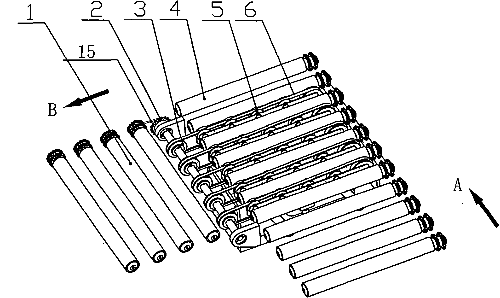
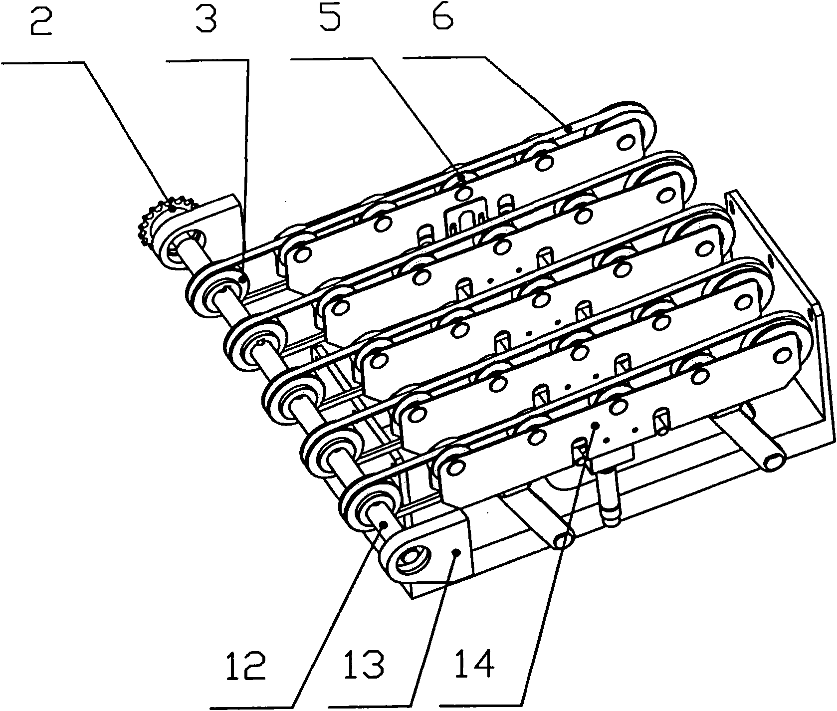
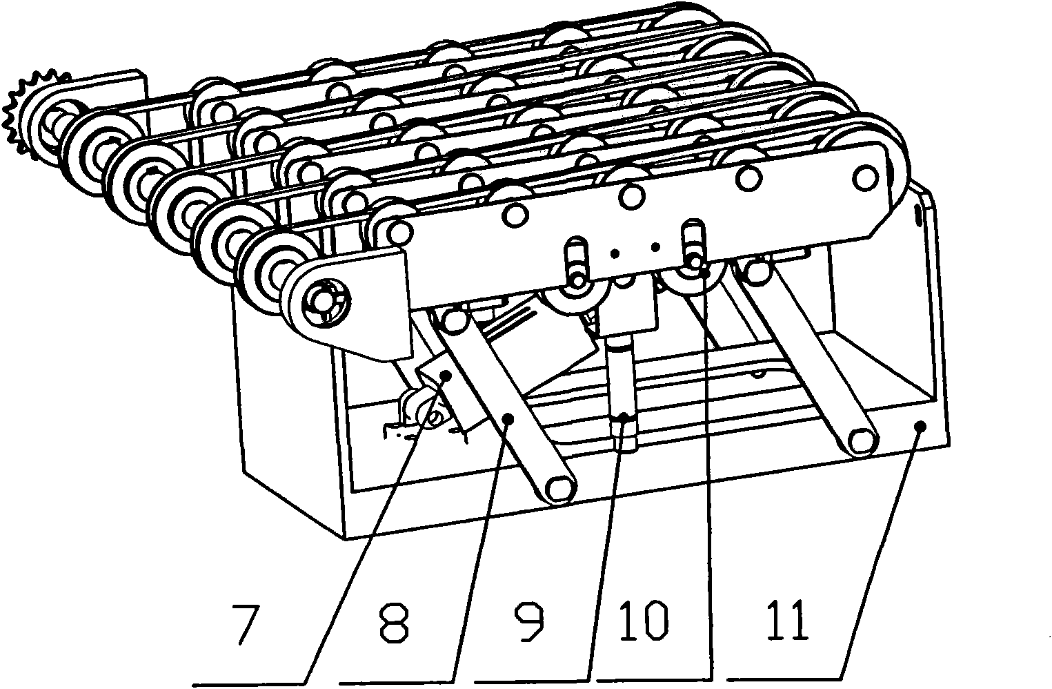
[0023] see Figure 1~3 , figure 1 It is a schematic diagram of the overall structure of the material distribution mechanism of the present invention. figure 2 It is a structural diagram of the state of the lane-dividing mechanism of the present invention. image 3 It is a structural diagram of the second state of the lane-dividing mechanism of the present invention. Depend on figure 1 , figure 2 and image 3 It can be seen that the material diverting mechanism of the present invention includes a first conveying raceway 4, a second conveying raceway 1 and a lane dividing mechanism, the first conveying raceway 4 and the second conveying raceway 1 are arranged at an angle of 90°, The lane-dividing mechanism is arranged at the turning point of the first conveying raceway 4 and the second conveying raceway 1, and placed under the first conveying raceway 4. The lane-dividing mechanism includes a fixed seat body 11, a bearing seat body 13, a Shaft 12, drive sprocket 2, drive ...


PUM


Abstract

The invention relates to a material diversion mechanism, which is used in a material diversion system of a roller conveyer line and comprises a first conveying roller path (4), a second conveying roller path (1) and a path separation mechanism. An angle of 90 degrees is formed between the first conveying roller path (4) and the second conveying roller path (1). The path separation mechanism is arranged at the turning point of the first conveying roller path (4) and the second conveying roller path (1), is arranged under the first conveying roller path (4) and comprises a fixed seat body (11), a bearing seat body (13), a driving shaft (12), a driving sprocket (2), a driving belt pulley (3), a belt bearing body (14), a belt bearing wheel (5), connecting rods (8), a lifting cylinder (7), a tension adjusting cylinder (9) and a tension adjusting wheel (10), wherein the belt bearing body (14), the belt bearing wheel (5), the driving belt pulley (3) and a belt (6) form a belt conveyor unit, and the fixed seat body (11), the two groups of connecting rods (8) and the belt conveyor unit jointly form a parallelogram mechanism. The material diversion mechanism improves the material diversion efficiency and can protect materials against damages during diversion.

Description

1) Technical field [0001] The invention relates to a material splitting mechanism. This mechanism is widely used in the material distribution system of the roller conveyor line, including the distribution of materials such as cartons, woven bags, plastic bags, and pallets. It belongs to the technical field of packaging machinery. (2) Background technology [0002] At present, cartons, woven bags, plastic bags, pallets, etc. on the market mainly use cylinders to push materials to realize the diversion of materials. The main defects of this product are: [0003] 1. As the width of the material conveying line changes, the stroke of the cylinder must change accordingly to push the material to the branch conveying line, resulting in an increase in the cost of the cylinder. [0004] 2. One material is pushed to the branch conveying line by the cylinder. After the cylinder retracts to the initial position, the next material can continue to be conveyed to the pushing position of t...

Claims


Application Information

Patent Timeline
IPC IPC(8): B65B35/54B65B35/42B65G47/72
Inventor 孙龙盛军杜飞
Owner 江阴纳尔捷机器人有限公司
Learn More