Building method of integral slip type scaffold used for steel grid construction

A scaffolding and steel grid technology, applied in the direction of construction, building structure, housing structure support, etc., can solve the problems of complicated construction, insufficient stability, complex sliding scaffolding structure, etc. Effect of rack installation safety factor

Active Publication Date: 2010-10-27
BUILDING & MOUNTING ENG CO LTD NO 12 BUREAU MINIST OF RAILWAYS +2
View PDF5 Cites 14 Cited by
  • Summary
  • Abstract
  • Description
  • Claims
  • Application Information

AI Technical Summary

Problems solved by technology

[0004] In order to solve the problem that various construction methods adopted in the construction of existing grid structures have their own shortcomings, especially for the problems of complex structure, cumbersome construction and insufficient stability of existing sliding scaffolding, the present invention provides a steel grid structure Construction method of overall sliding scaffolding for construction

Method used


Image

  • Building method of integral slip type scaffold used for steel grid construction
  • Building method of integral slip type scaffold used for steel grid construction
  • Building method of integral slip type scaffold used for steel grid construction

Examples


example 1

[0032] Project example 1: Painting workshop project of civil ship project of CSSC Longxue Shipbuilding Base (construction date: July 2007-September 2008)

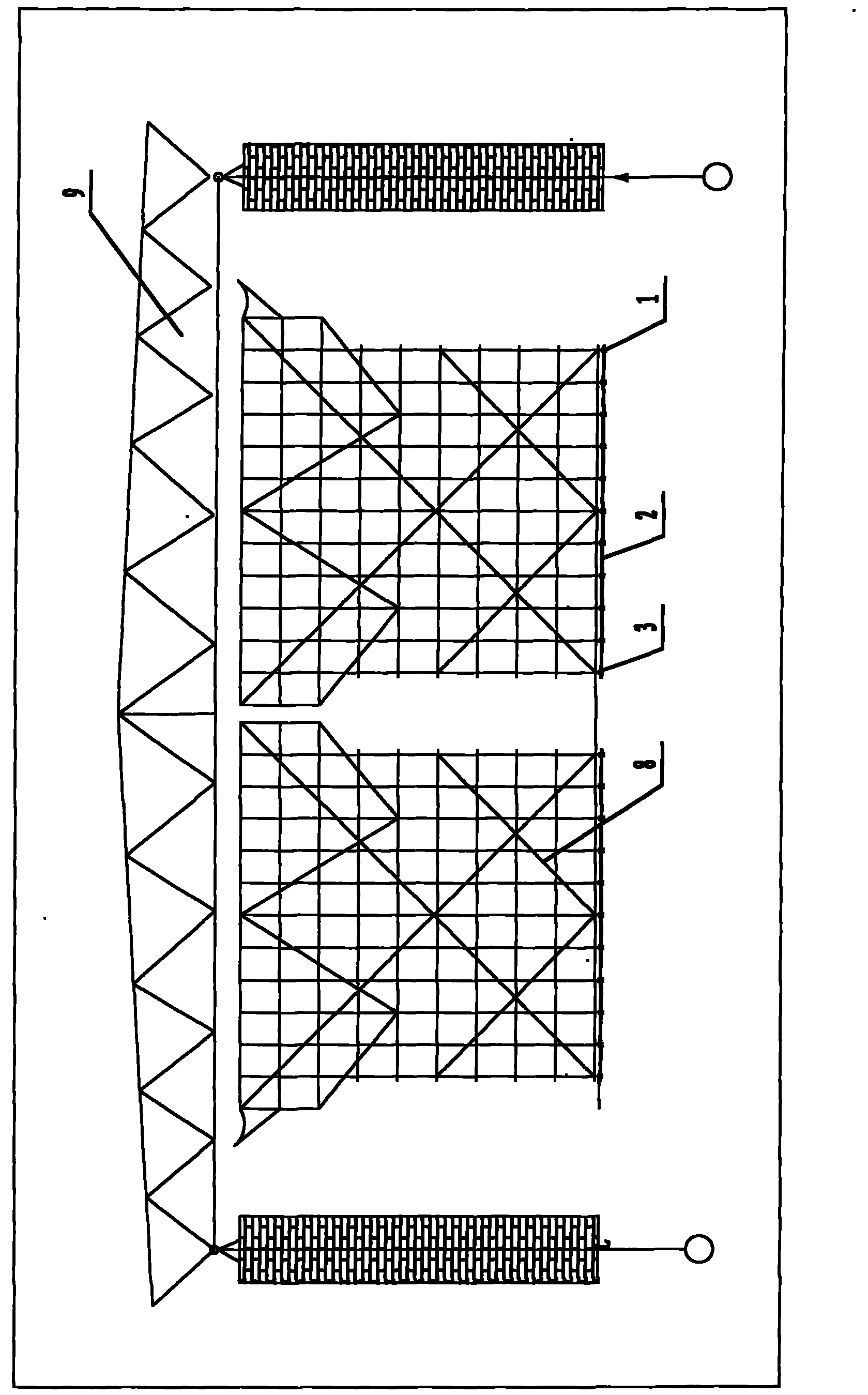
[0033] This project includes two single units, the sandblasting workshop and the painting workshop, with a total construction area of ​​44968m2 2 . Build two single-story multi-span steel structure workshops (sandblasting workshop and painting workshop) and a painting storage yard within the scope of the land, and the sandblasting workshop covers an area of ​​16765m 2 , construction area 24258m 2 , the workshop span is 30m×6, and the partial height of the building is 21.15m; the painting workshop covers an area of ​​15984m 2 , construction area is 20710m 2 , the workshop span is 30m×7, the partial height of the building is 21.15m; the coating yard area is 28000m 2 , asphalt concrete floor.

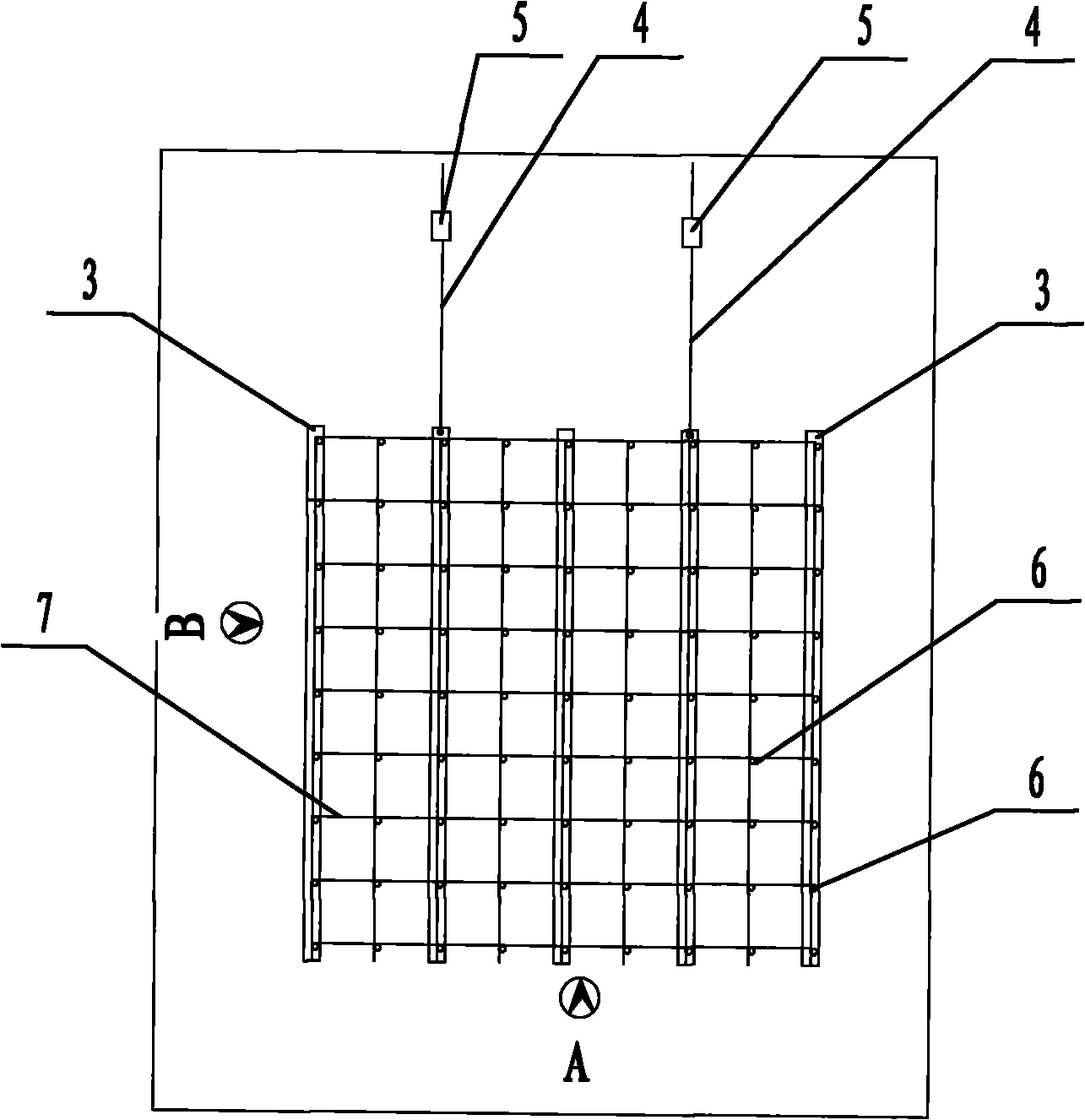
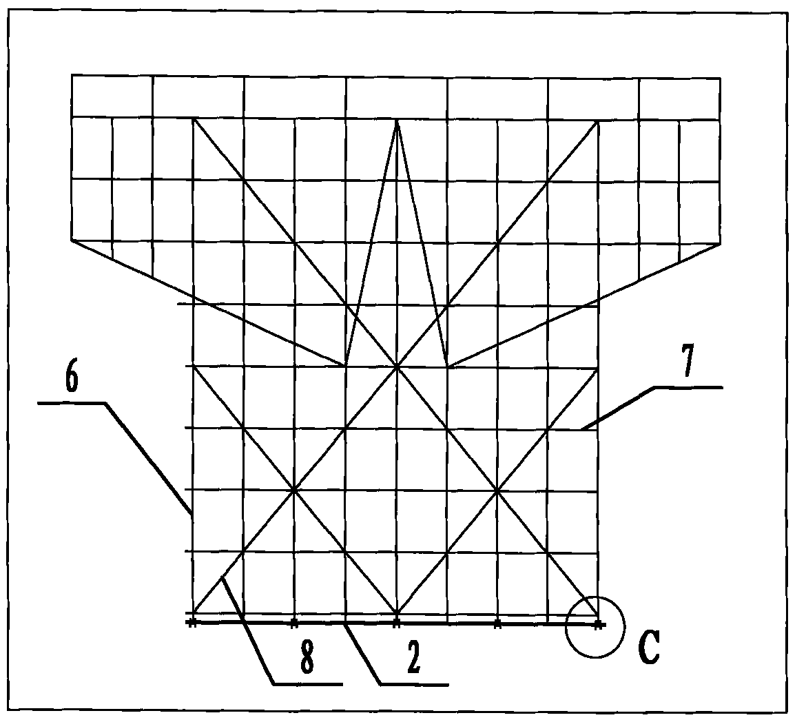
[0034] The middle machine room is a reinforced concrete structure, with corbels as supporting points, and the workshop is a grid ...

example 3

[0040] Project example 3: Painting workshop project in marine area of ​​CSSC Longxue shipbuilding base (construction date: January 2009-October 2009)

[0041] The project is divided into two areas according to functions: sandblasting room and painting room. The sandblasting room includes three intermediate machine rooms, one rear machine room, and two sandblasting rooms. The crane single-storey factory building has a plane axis size of 24m×42m; the painting workshop includes four intermediate machine rooms and three painting rooms. The total axis size is 42m×120.7m, and the main workshop is a single-storey factory building without a crane, and its plane axis size is 24m×42m. The structure of the middle machine room and the rear machine room of the painting room and sandblasting room are all reinforced concrete frame structures, with a total area of ​​9818m2 2 , with a total construction area of ​​15743m 2 , of which the blasting room is 7921m 2 , paint booth 7822m 2 , the ...


PUM


Abstract

The invention relates to a device for steel grid construction, in particular to a building method of an integral slip type scaffold used for steel grid construction, which solves the problem that the existing various construction methods for grid construction have respective shortcomings. The method comprises the steps of fixing channel steel guide rails; arranging steel tube guide wheels vertical to the guide rails at intervals on each channel steel guide rail; paving channel steel slip bases coincident with each channel steel guide rail on the steel tube guide wheel, and arranging a drawing head connected with a drawing device via wire ropes on the channel steel slip base; erecting a standing bar; longitudinally and transversely erecting horizontal cross bars; erecting a scissors brace; and paving an operating platform. The invention has the advantages of simple erection, stable integral structure, greatly increased slip efficiency, easy operation and high slip safety, has small influence on periphery construction and production environment, has construction continuity, can fully guarantee the quality of grid installation and the construction of other types of work, saves time and labor, ensures the construction safety, and increases the construction efficiency.

Description

technical field [0001] The invention relates to a steel grid construction equipment, in particular to a construction method of an integral sliding scaffold for steel grid construction. Background technique [0002] The grid structure is light in weight, high in rigidity, good in mechanical properties, good in shock resistance, and high in design, manufacturing and installation precision. The grid structure can be used for buildings with a span of more than 100 meters and door decorations or billboards with a span of a few meters. The grid structure has been developed in China for more than ten years, and it has been widely used in industrial plants, gymnasiums, supermarkets and small gas stations. The construction method of the grid frame is based on the stress and structural characteristics of the grid frame, the rigidity of the grid frame, the appearance characteristics of the grid frame, the support form, the support structure, etc., and meets the quality, safety, constr...

Claims


Application Information

Patent Timeline
Patent Type & Authority Applications(China)
IPC IPC(8): E04G1/24E04G1/04
Inventor 王兆强李靖滨林联远
Owner BUILDING & MOUNTING ENG CO LTD NO 12 BUREAU MINIST OF RAILWAYS
Why Eureka
Try Eureka