Fan wheel structure and manufacturing method thereof

A technology of fan wheel and hub, applied in the field of fan wheel structure and its manufacturing, can solve the problems of poor uniformity, increased working hours, and different quality.

Inactive Publication Date: 2010-10-27
ASIA VITAL COMPONENTS (CHINA) CO LTD
View PDF0 Cites 2 Cited by
  • Summary
  • Abstract
  • Description
  • Claims
  • Application Information

AI Technical Summary

Problems solved by technology

[0008] 1. High production cost
[0009] 2. Increase working hours
[0010] 3. Slow production speed
[0011] 4. Poor uniformity
[0012] 5. Different quality

Method used


Image

  • Fan wheel structure and manufacturing method thereof
  • Fan wheel structure and manufacturing method thereof
  • Fan wheel structure and manufacturing method thereof

Examples


Embodiment Construction

[0041] The above-mentioned purpose of the present invention and its structural and functional characteristics will be described according to the preferred embodiments of the accompanying drawings.

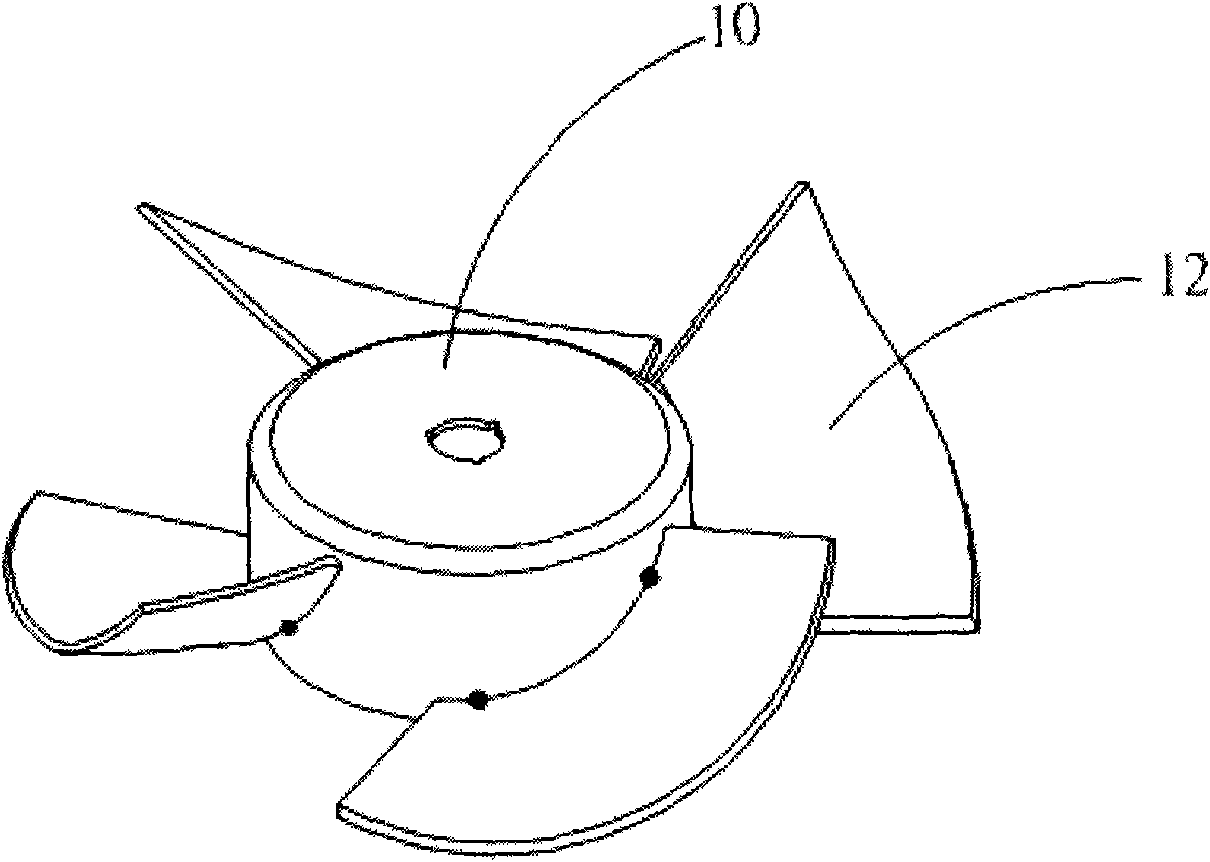
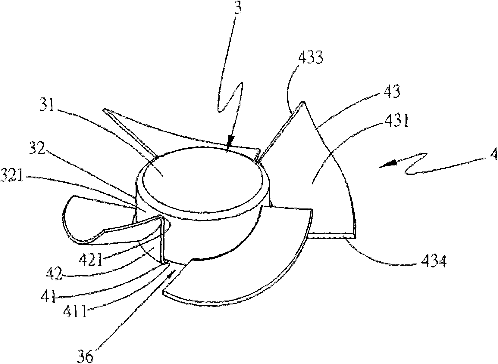
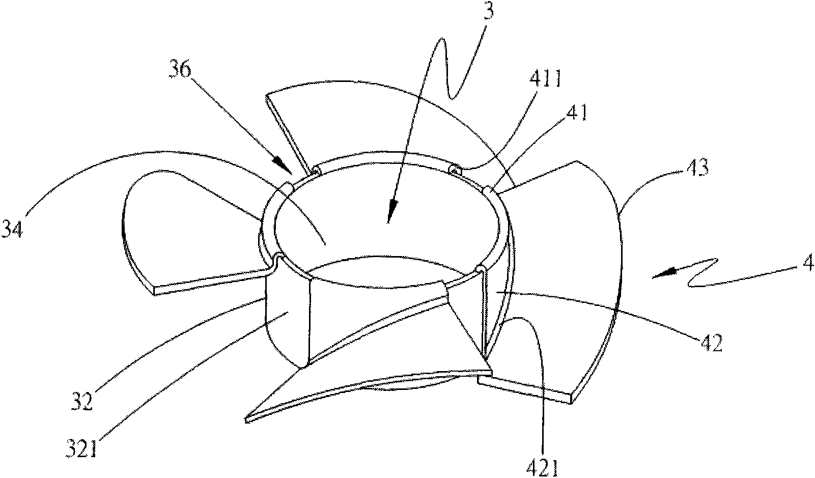
[0042] Please also refer to figure 2 , 2A As shown, the present invention is a fan wheel structure and its manufacturing method. In a preferred embodiment of the present invention, the fan wheel structure is made of metal materials, such as iron, aluminum, copper and metal alloys, and The fan wheel structure includes a hub 3 and at least one blade 4. The aforementioned hub 3 has a first portion 31 and a second portion 32 extending along the periphery of the first portion 31. One end of the first portion 31 is connected to one end of the second portion 32. , and define a hollow space 34, the aforesaid hollow space 34 is to accommodate the sleeve base and its motor in a fan frame (not shown in the figure), and it relatively covers the sleeve base and its motor (not shown in the fig...


PUM


Abstract

The invention provides a fan wheel structure and a manufacturing method thereof. The fan wheel structure is made of metal and comprises a hub and at least one blade, wherein the hub is provided with a first part and a second part which stretches along the periphery of the first part; one end of the first part is connected with one end of the second part and defines a hollow space; the blade is provided with a connection part, a support part and a wind guide part, wherein the connection part stretches towards the other end of the second part; and the support part is arranged at the outer side of the periphery of the second part, one end of the support part is connected with the connection part and the other end thereof is connected with the wind guide part to form the blade, thus obtainingthe fan wheel structure of the invention.

Description

technical field [0001] The present invention relates to a fan wheel structure and a manufacturing method thereof, in particular to a fan wheel structure and a manufacturing method thereof that can improve the overall fan wheel structure to achieve better uniformity in manufacturing, save production costs and reduce man-hours. Background technique [0002] In recent years, with the development of the electronics industry, the performance of electronic components has improved rapidly, and the processing speed has become faster and faster, and the calculation speed of the internal chipset has been continuously improved, and the number of chips has also continued to increase. The heat of the electronic components also increases accordingly. If these heat sources are not dissipated in time, it will greatly affect the performance of the electronic components, reduce the computing and processing speed of the electronic components, and as the heat continues to accumulate, the electro...

Claims


Application Information

Patent Timeline
Patent Type & Authority Applications(China)
IPC IPC(8): F04D29/32F04D29/38B21D22/02
Inventor 吴文胜吴仁捷
Owner ASIA VITAL COMPONENTS (CHINA) CO LTD
Why Eureka
Try Eureka