Ball valve

A ball valve and valve body technology, applied in the direction of valve devices, cocks including cut-off devices, engine components, etc., can solve the problems of small operating range, bending and deformation of positioning pins, affecting the opening of the ball valve, etc.

Inactive Publication Date: 2010-10-27
ZHEJIANG SANHUA CO LTD
View PDF0 Cites 8 Cited by
  • Summary
  • Abstract
  • Description
  • Claims
  • Application Information

AI Technical Summary

Problems solved by technology

[0005] During use, the positioning pin is often bent and deformed due to the large operating torque, which affects the control of the opening of the ball valve, and the stability of the ball valve is poor.
For ball valves with this structure, it is usually necessary to increase the cross-sectional dimensions of related components such as positioning pins and valve stems to increase the flexural section modulus of the positioning pins; Larger assembly space required
In particular, for ball

Method used


Image

  • Ball valve
  • Ball valve
  • Ball valve

Examples


Embodiment Construction

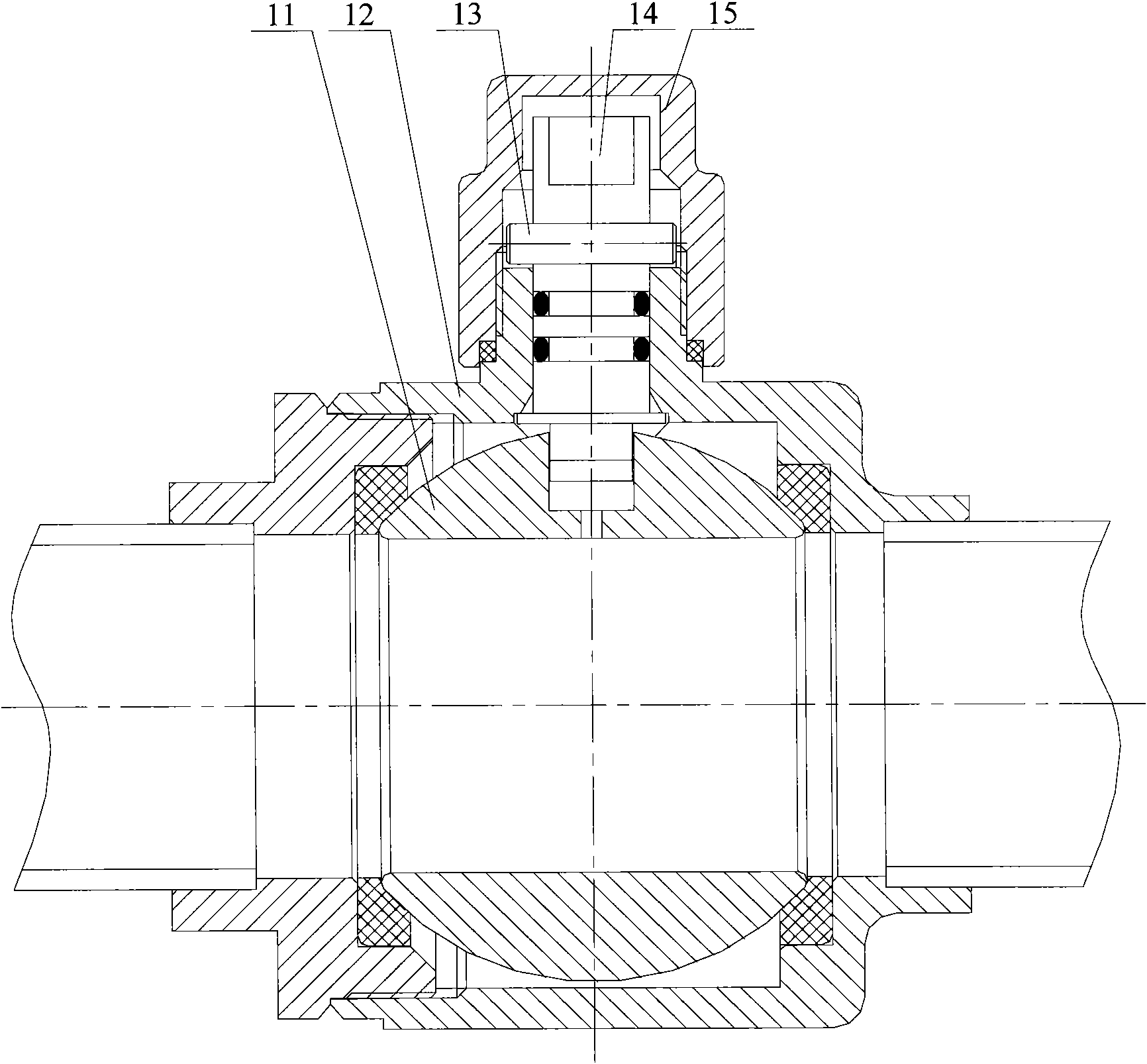
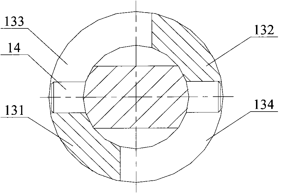
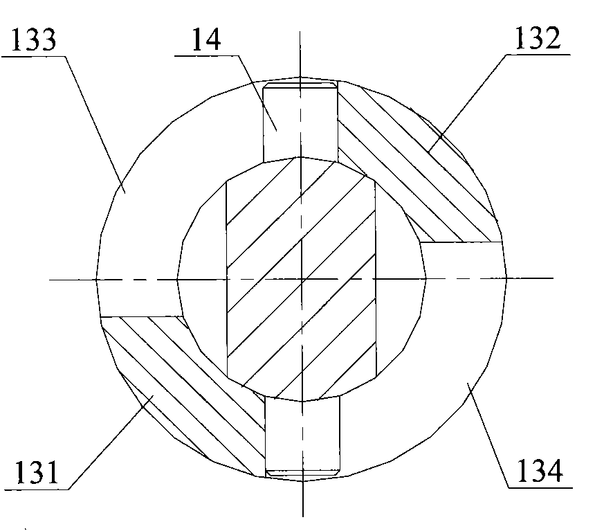
[0032] The present invention is a structural improvement design based on the existing ball valve. It includes a stop part arranged on the valve stem and a positioning boss arranged on the valve body, and the protruding part of the stop part cooperates with the positioning boss , In order to limit the fully open position and fully closed position of the ball valve; compared with the existing ball valve, the main point of the design of the present invention is that the bending section of the extension of the stop member is rectangular, and the rectangular bending section is high The width ratio h / b satisfies: 1

[0033] The height h and width b dimensions of the rectangular bending section mentioned in this article are based on the section figure when the force analysis of the extension is carried out (see Figure 7 ) Is defined as a benchmark.

[0034] Hereinafter, this embodiment will ...


PUM


Abstract

The invention discloses a ball valve comprising a locking part and a positioning boss, wherein the locking part is arranged on a valve rod, and the positioning boss is arranged on the valve body; the extending part of the locking part is matched with the positioning boss so as to limit the full-open position and the full-closed position of the ball valve; the anti-bending section of the locking part is rectangular, and the height-breadth ratio h/b of the rectangle anti-bending section satisfies the condition that h/b is less than 6 and is more than 1; the ball valve has better anti-bending property. Preferably, the positioning boss is provided with a first positioning surface and a second positioning surface, the deflection angle for the locking part to extend between the first positioning surface and the second positioning surface is 180 degrees; when the extending part rotates to the middle position between two positioning surfaces, the ball valve is in the full-open position and the full-closed position; when the extending part rotates to the position on which the side end surface is abutted with the first positioning surface or the position on which the other end surface is abutted with the second positioning surface, the ball valve is in the full-open position and the full-closed position. Thus, the valve rod can rotate within the range of 180 degrees so as to greatly improve the adaptability and the maneuverability of the ball valve.

Description

Technical field [0001] The invention relates to a ball valve, in particular to a ball valve used in a pipeline system. Background technique [0002] In the refrigeration system, the refrigerant delivery pipeline generally needs to be equipped with a ball valve to realize the cut-off or conduction of the refrigerant transmission path. [0003] See figure 1 , This figure is a schematic diagram of the overall structure of the existing ball valve. [0004] During the opening and closing operation of the existing ball valve, the valve stem 14 drives the ball 11 to rotate in the valve body 12. The deflection angle of the ball 11 from the fully open position to the fully closed position is approximately 90°. Therefore, the ball 11 is in the valve body. The angle of rotation within 12 needs to be limited. Such as figure 1 As shown, the existing ball valve uses a positioning pin 13 as a stop component to cooperate with a positioning boss to realize the limit of the switch, wherein the posit...

Claims


Application Information

Patent Timeline
IPC IPC(8): F16K5/06F16K5/08
Inventor 郑旭锋王喜忠
Owner ZHEJIANG SANHUA CO LTD
Why Eureka
Try Eureka