Photo sensor based on vernier effect of broadband light source and cascading optical waveguide filter
A broadband light source and optical sensor technology, which is applied in the direction of using optical devices to transmit sensing components, light guides, fluid pressure measurement using optical methods, etc., can solve the problems of increasing the cost of measuring devices and reducing reliability, so as to increase sensitivity and reduce cost effect
- Summary
- Abstract
- Description
- Claims
- Application Information
AI Technical Summary
Problems solved by technology
Method used
Image
Examples
Embodiment 1
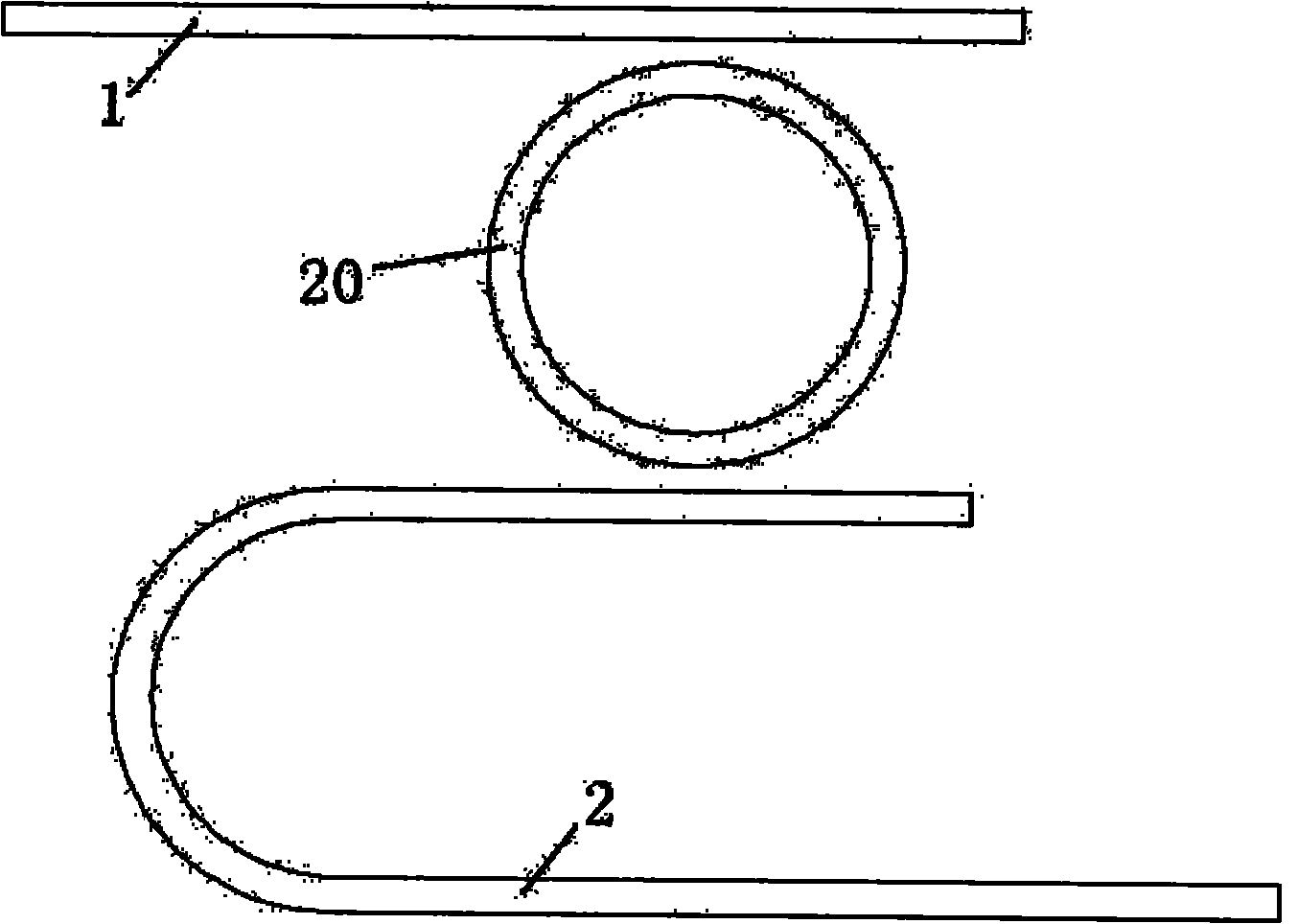
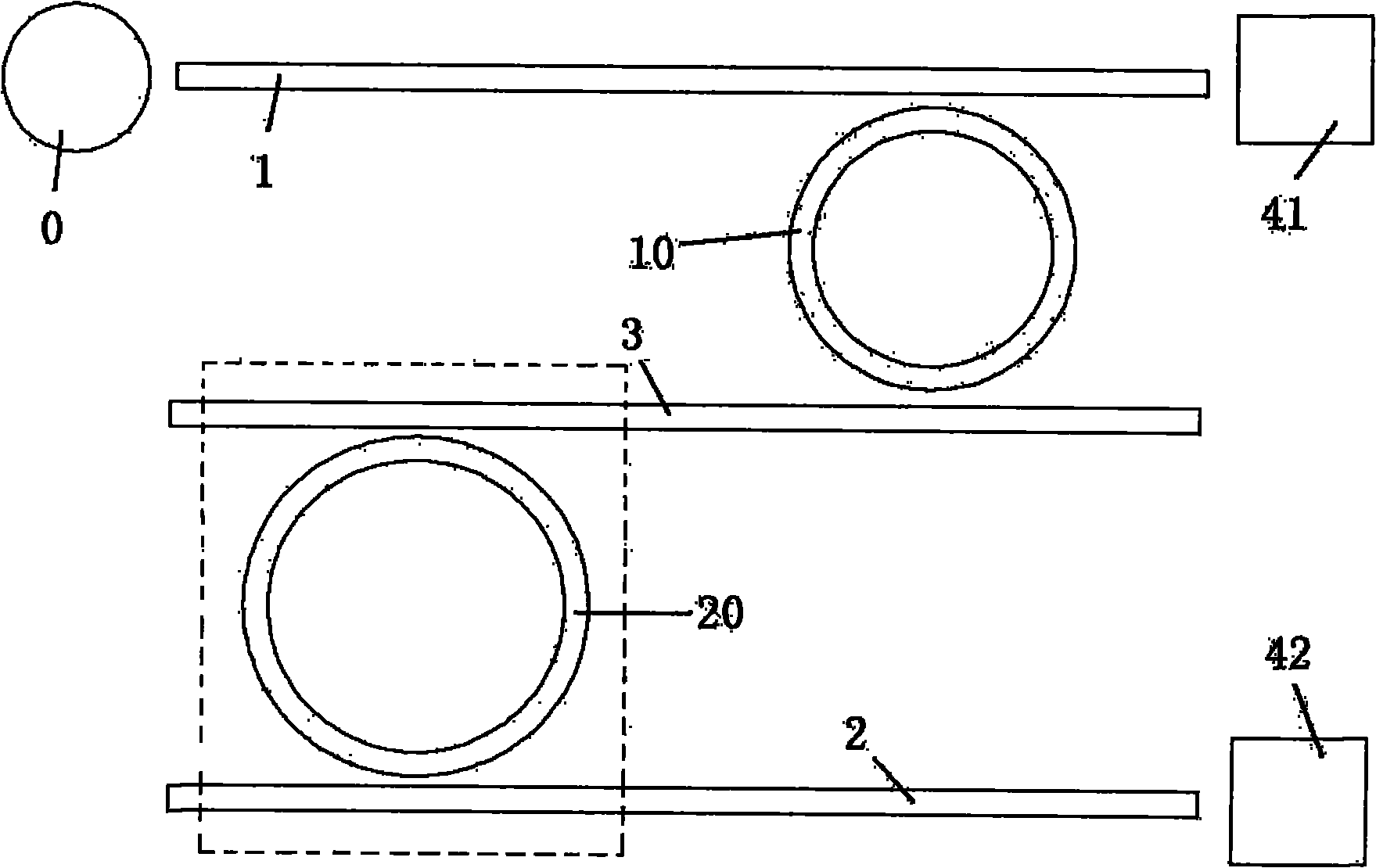
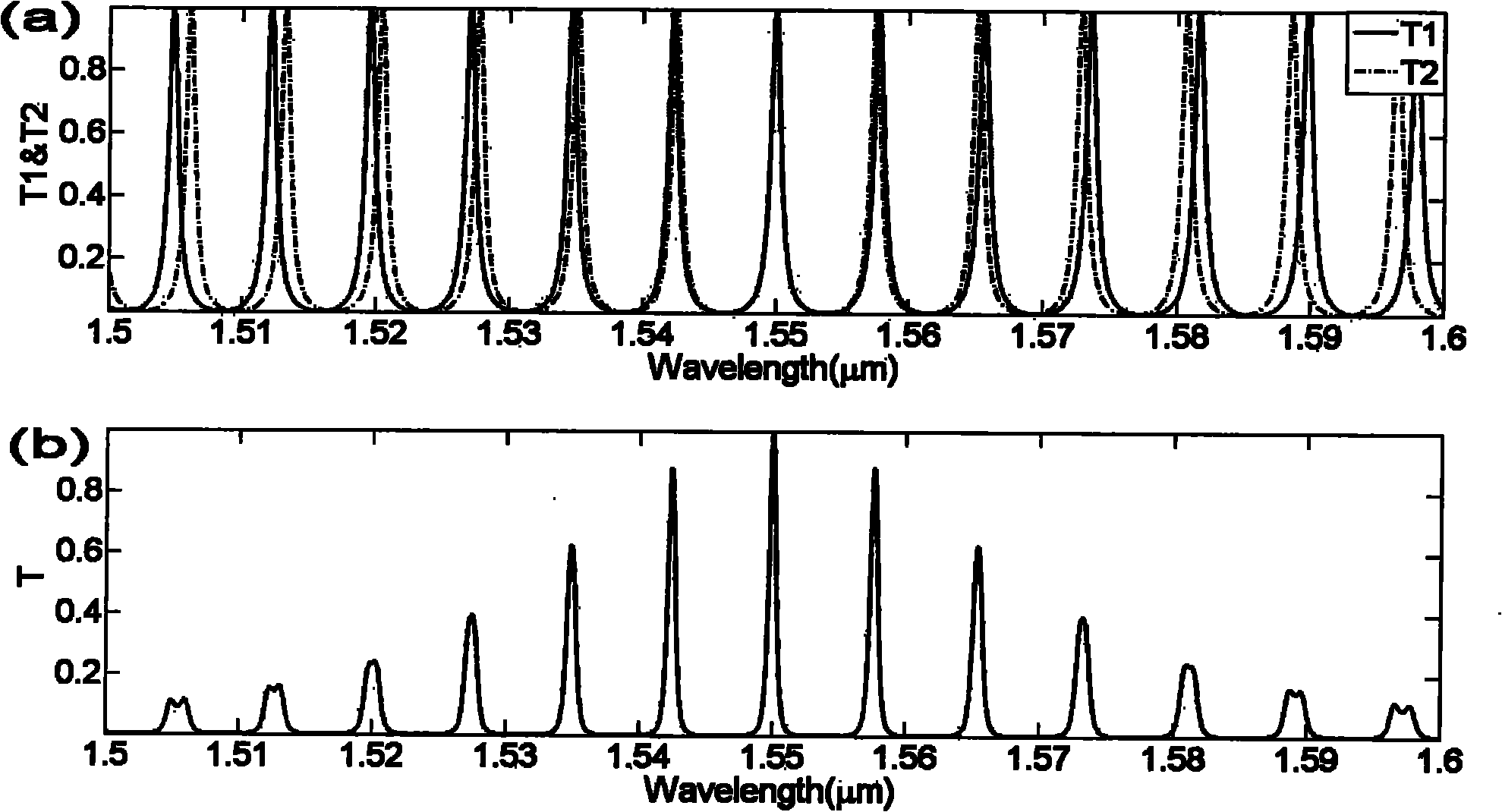
[0033] figure 2 It is a schematic diagram of the first embodiment of the present invention. It includes a broadband light source 0, an input waveguide 1 coupled with the broadband light source, a reference ring resonator 10 coupled with the input waveguide 1, a connection waveguide 3 coupled with the reference ring resonator 10, and a transmission waveguide coupled with the connection waveguide 3. Sensing ring resonator 20, output waveguide 2 coupled with sensing resonator 20, power meter 41 for measuring the output power at the other end of input waveguide 1, and power meter 42 for measuring the output power of output waveguide 2, the reference ring resonator 10 Unlike the optical length of the sensing ring resonator 20, the optical length of the reference ring resonator 10 is such that its resonant frequency corresponds to a series of equally spaced operating frequencies, the optical length of the sensing ring resonator 20 is such that When one of its resonant frequencies ...
Embodiment 2
[0058] Figure 8 It is a structural schematic diagram of the second embodiment of the present invention. It includes a broadband light source 0, an input waveguide 1 coupled with the broadband light source, a reference ring resonator 10 coupled with the input waveguide, a connection waveguide 3 coupled with the reference ring resonator 10, and a sensor coupled with the connection waveguide 3. Ring resonator 20, output waveguide 2 coupled with sensing resonator 20, optical power meter 41 for measuring the output power at the other end of input waveguide 1, and optical power meter 42 for measuring the output power of output waveguide 2, the reference ring resonator 10 is different from the optical length of the sensing ring resonator 20, the optical length of the reference ring resonator 10 makes its resonant frequency correspond to a series of equally spaced operating frequencies, the optical length of the sensing ring resonator 20 When one of its resonant frequencies overlaps...
Embodiment 3
[0062] The ring resonator among the present invention is to play the effect of an optical filter, has the advantage of high quality factor (Q value), but the ring resonator can be formed by a Mach-Zehnder (Mach-Zehnder) interferometer, array Filters such as waveguide gratings, Bragg gratings, or Fabry-Perot (Fabry-Perot) interferometers can be used instead, wherein the Fabry-Perot (Fabry-Perot) interferometer can be composed of two Bragg gratings.
[0063] Such as Figure 9 As shown, it includes a broadband light source 0, an input waveguide 1 coupled with the broadband light source, a reference optical filter 101 coupled with the input waveguide, a connection waveguide 3 coupled with the reference optical filter 101, and a transmission waveguide coupled with the connection waveguide 3 A sensing optical filter 102, an output waveguide 2 coupled with the sensing optical filter 102, an optical power meter 42 for measuring output power, the transmission frequency of the reference...
PUM
| Property | Measurement | Unit |
|---|---|---|
| refractive index | aaaaa | aaaaa |
| refractive index | aaaaa | aaaaa |
Abstract
Description
Claims
Application Information
 - R&D
- Intellectual Property
- Life Sciences
- Materials
- Tech Scout
- Unparalleled Data Quality
- Higher Quality Content
- 60% Fewer Hallucinations
Browse by: Latest US Patents, China's latest patents, Technical Efficacy Thesaurus, Application Domain, Technology Topic, Popular Technical Reports.
© 2025 PatSnap. All rights reserved.Legal|Privacy policy|Modern Slavery Act Transparency Statement|Sitemap|About US| Contact US: help@patsnap.com


