Laser bonding device

A technology of laser welding and laser devices, which is applied in laser welding equipment, lasers, welding equipment, etc., and can solve the problems of complex connection between coated wires and terminals

Inactive Publication Date: 2010-10-27
SUMITOMO WIRING SYST LTD
View PDF1 Cites 7 Cited by
  • Summary
  • Abstract
  • Description
  • Claims
  • Application Information

AI Technical Summary

Problems solved by technology

Therefore, even in the case of laser welding of coated wires and terminals, it is necessary to perform coating removal work using a laser device for surface processing and coating wire and terminals using a laser device for welding separately. Laser welding connection, so the connection work of the coated wire and the terminal becomes complicated

Method used


Image

  • Laser bonding device
  • Laser bonding device
  • Laser bonding device

Examples


Embodiment Construction

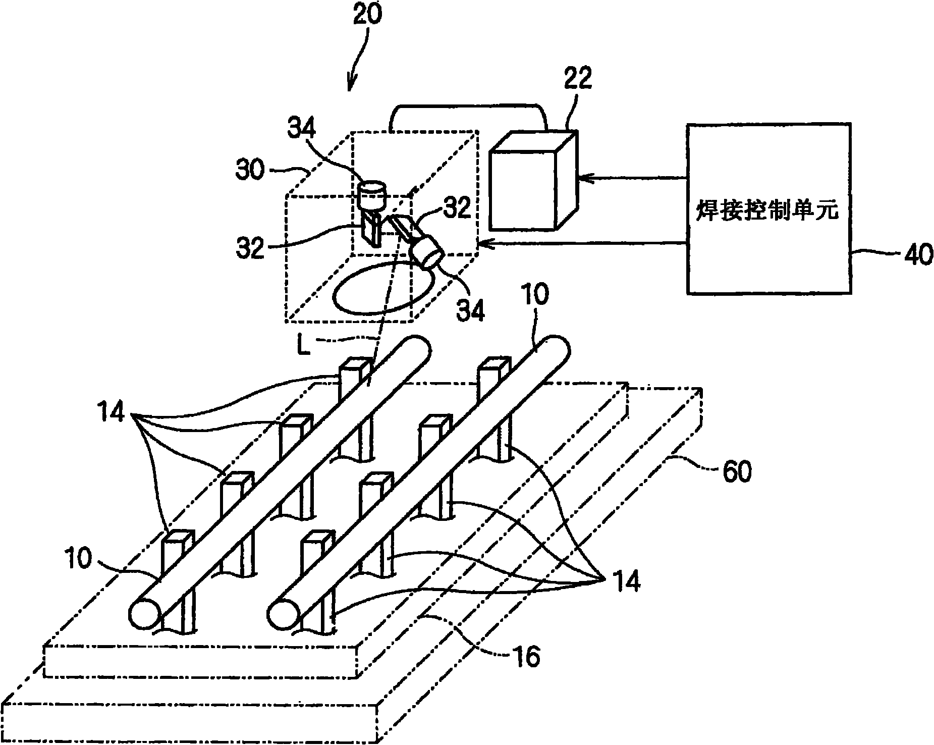
[0027] Hereinafter, the laser welding device according to the embodiment will be described. figure 1 It is a schematic diagram showing the laser welding device 20 .

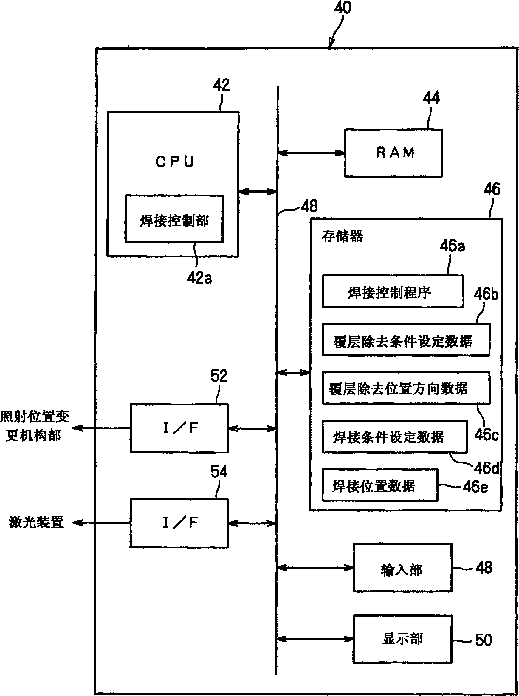
[0028] This laser welding device 20 is a device that connects the coated wire 10 and the terminal 14 by laser welding after removing the coating of the coated wire 10, and includes a laser device 22, an irradiation position changing mechanism part 30, and Welding control unit 40 .

[0029] Here, a specific example of welding objects will be described. The plurality of terminals 14 are elongated members formed of copper, annealed copper, or the like. One end of each terminal 14 is connected to the coated wire 10 as described later, and the other end of each terminal 14 can be electrically connected to other electronic components (power semiconductor elements, relays, fuses, connectors, etc.). The coated wire 10 is formed by coating the surface of a wire such as a copper wire or an annealed copper wire with an i...


PUM


Abstract

A laser bonding device can rapidly and conveniently remove a cover layer on a lead with cover layer and perform the laser bonding on the lead and a terminal. The laser bonding device can perform laser bonding on the lead with cover layer (10) and the terminal (14). The laser bonding device (20) is provided with a laser device (22) for generating a laser (L), an illuminating position exchanging mechanism (30) for changing the illumination position of the laser (L), and a bonding control unit (40) for controlling the illuminating position exchanging mechanism (30) to illuminate the laser (L) from the laser device (22) to a bonding area surface of the lead with cover layer (10), so as to illuminate the bonding object points of the lead with cover layer (10) and the terminal (14) through the laser (L) from the laser device (22) after covering the bonding area surface and perform the laser bonding on the lead with cover layer (10) and the terminal (14).

Description

technical field [0001] The invention relates to a laser welding technology for a coated wire and a terminal. Background technique [0002] In circuit components such as wiring harnesses for automobiles and electrical connection boxes (J / B (junction box), R / B (relay box), F / B (fuse box)), by properly connecting coated wires such as enameled wires with terminals connected to form a predetermined circuit. [0003] The above-described covered lead wire and terminal can be connected by laser welding without removing the coating of the covered lead wire. However, when the coated wire and terminal are laser welded without removing the coating, there is a possibility of quality degradation (poor contact, insufficient connection strength) due to the remaining carbonized coating, and due to the adhesion of carbon dust and the melting of the coating. Residues degrade the appearance, etc. In order to suppress this problem, it is preferable to remove the coating in advance when connec...

Claims


Application Information

Patent Timeline
Patent Type & Authority Applications(China)
IPC IPC(8): H01R43/02H01R43/28B23K26/21H01S3/00H02G1/12
Inventor 菊地佑介服部充博
Owner SUMITOMO WIRING SYST LTD
Why Eureka
Try Eureka