
Bearing washer

A bearing cleaning and cleaning room technology, which is applied in the direction of dust removal, cleaning methods and tools, cleaning methods using liquids, etc., can solve the problems that ordinary bearing cleaning machines cannot be effective, large-size bearings are troublesome to operate, and the operation labor intensity is low. Achieve the effects of low labor intensity of operation, improvement of product quality and service life, and high degree of automation

Inactive Publication Date: 2010-11-03
宁波达克轴承有限公司
View PDF6 Cites 56 Cited by
  • Summary
  • Abstract
  • Description
  • Claims
  • Application Information

AI Technical Summary

Problems solved by technology

[0004] The present invention provides a cleaning machine with high cleaning efficiency and labor-intensive operation to solve the current situation that the existing ordinary bearing cleaning machine cannot effectively, conveniently and quickly clean large-size bearings and the operation of the entire cleaning process is troublesome, which affects production efficiency and the variety of final bearing products. Bearing cleaning machine with low strength, can automatically complete the whole process of cleaning products, and clean thoroughly

Method used


Image

  • Bearing washer
  • Bearing washer
  • Bearing washer

Examples


Embodiment 1

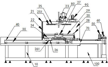
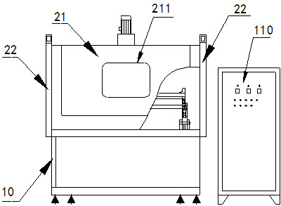
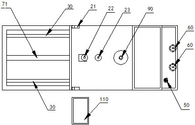
[0025] figure 1 , figure 2 , image 3 In the shown embodiment, a bearing cleaning machine includes a main workbench 10, a cleaning chamber 20 installed on the main workbench 10, a spray pump and a transmission motor 80, and the main workbench 10 is installed with the cleaning chamber 20. In and out track 30, the in and out material trolley 24 is installed on the in and out track 30, the in and out track 30 is connected with the in and out cylinder 70, the upper spray pipe 25 of the large-size bearing is installed at the top position in the cleaning room 20, the cleaning room 20 There is a lower spray pipe 26 at the bottom position of the bottom, and the lower spray pipe 26 is arranged under the feeding and discharging trolley 24, and the upper spraying pipe 25 and the lower spraying pipe 26 are connected with the spray pump 50; The inner fixing fixture 27 and the outer fixing fixture 28 and the upper transmission support frame 29 that are installed with adjustable clamping...

Embodiment 2

[0027] Lifting motor 22 is installed on cleaning chamber 20 tops (see Figure 4 , Figure 5 ), the internal fixing fixture 27 and the external fixing fixture 28 adopt a manual fixing and adjusting clamping structure. Adjust the inner fixing fixture 27 and the outer fixing fixture 28 to clamp and fix the inner and outer rings of the large-size bearing on the upper transmission support frame 29 . All the other are identical with embodiment 1.

Embodiment 3

[0029] Inner fixing fixture 27 and outer fixing fixture 28 and upper transmission support frame 29 adopt the material structure of iron metal material structure outer cover oil resistance, anti-bearing bump, as plastic material structure. All the other are identical with embodiment 1.

[0030] When preparing to clean, enter and exit the cylinder to drive the inner and outer fixing fixtures of the inner and outer bearings and the uploading support frame 29 to the position of the loading and unloading table 40, hang the large-size bearing on the uploading support frame 29 by a crane, and start the motor to adjust the internal The positions of the fixing fixture 27 and the outer fixing fixture 28 are such that the inner ring of the large-size bearing is fixed by the inner fixing fixture 27, the outer ring is fixed by the outer supporting fixture 28, and the entire inner and outer fixing fixtures and the uploading support frame 29 are fixed on the feeding and discharging trolley A...


PUM

PropertyMeasurementUnit
Angleaaaaaaaaaa

Abstract

The invention discloses a bearing washer, which comprises a main body workbench, a washing chamber arranged on the main body workbench, a spraying pump and a drive motor, wherein the main body workbench is provided with an inlet-outlet path of the washing chamber; the inlet-outlet path is provided with a feed-discharge trolley; the inlet-outlet path is connected with an inlet-outlet cylinder; an upper spraying pipe is arranged at the top position in the washing chamber, and a lower spraying pipe is arranged at the bottom position in the washing chamber; the feed-discharge trolley is provided with an inner stationary fixture, an outer stationary fixture and an upper drive carriage, and the inner and outer stationary fixtures can adjust and clamp a large-size bearing; a rotary spindle, which can be jointed with the centre of the inner stationary fixture, is arranged at the top position in the washing chamber; and the rotary spindle is connected with the drive motor. The bearing washer has the advantages of reducing intermediate links, automatically completing the whole process of product washing, effectively washing dead corners in the products, greatly improving the cleanness of the product, along with high automation, high washing efficiency, low operation and labor intensity, quick, convenient and flexible clamping and fixing operation and complete washing.

Description

technical field [0001] The invention relates to a bearing cleaning machine, in particular to a bearing cleaning machine for cleaning large-size bearings. Background technique [0002] Large-scale bearings are usually used in large-scale equipment, and after the large-scale bearings have undergone multiple production and processing processes, there is a certain degree of oil and trace waste. There is no way to meet the requirements for effective cleaning of large-size bearings. The traditional method is to use manual cleaning. The bearing can only be hoisted by a crane and the oil pump is used to inject the cleaning liquid into the hose. Manually hold the hose to spray the cleaning liquid onto the bearing. , to achieve the purpose of cleaning. A large iron box is used under the bearing to receive the used cleaning solution. There is an outlet at the bottom of the iron box to guide the used cleaning solution into the filter. The filter will filter out the impurities in the us...

Claims


Application Information

Patent Timeline
IPC IPC(8): B08B3/02B08B13/00B08B15/04
Inventor 梁晓东
Owner 宁波达克轴承有限公司
Learn More