
Ring crane corbel for nuclear power station and manufacturing method thereof

A manufacturing method and technology for nuclear power plants, which are applied to load hanging components, supporting structures, buildings, etc., can solve the problems of large welding workload, easy cracking of welds, large welding stress and welding deformation, etc., and achieve weld quality. Control, ensure the final quality, the effect of welding deformation control

Active Publication Date: 2010-11-03
CHINA NUCLEAR IND HUAXING CONSTR
View PDF5 Cites 14 Cited by
  • Summary
  • Abstract
  • Description
  • Claims
  • Application Information

AI Technical Summary

Problems solved by technology

[0003] The main structure of the ring-hanging corbel is a large box-type frame with a net weight of about 2 tons. The thickest steel plate is 60mm thick. Most of the welds are in the form of full penetration. The welding workload is large and the welding deformation is difficult to control. The welding stress is large, and the weld is prone to cracks
Due to the large amount of welding and the degree of restraint of the box-shaped structure, it is easy to generate large welding stress and welding deformation, resulting in product failure

Method used


Image

  • Ring crane corbel for nuclear power station and manufacturing method thereof
  • Ring crane corbel for nuclear power station and manufacturing method thereof
  • Ring crane corbel for nuclear power station and manufacturing method thereof

Examples


Embodiment 1

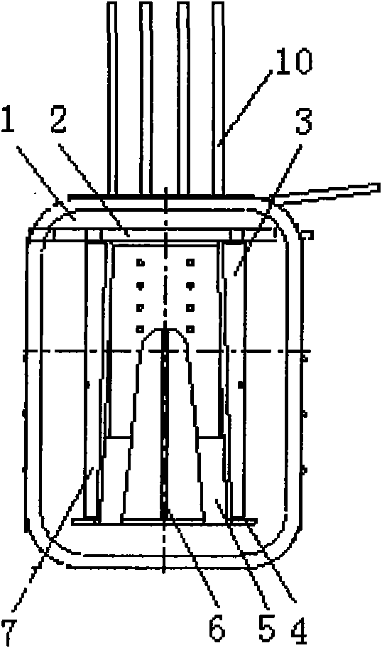
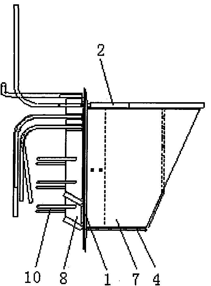
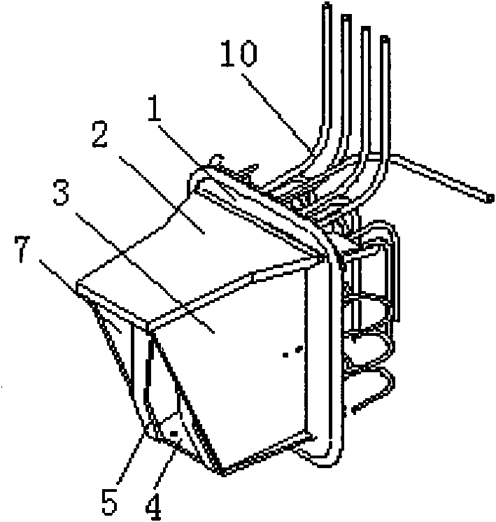
[0025] The basic structure of a ring-hanging corbel of a nuclear power plant in this embodiment is as follows: Figure 1 to Figure 4 As shown, the box frame body comprises rectangular thickened body panels 1 . One side of the main body plate 1 is adjacent to the upper and lower edges, and the upper cover plate 2 and the lower cover plate 4 perpendicular thereto are respectively welded and fixed, wherein the upper cover plate 2 is longer than the lower cover plate 4 . The trapezoidal left and right side plates 7 and 3 and the rectangular middle rib 6 are welded between the upper and lower cover plates, and the edges of the left and right side plates and the middle rib plate adjacent to the main body plate 1 are fully welded to the main body plate . The two ends of the side of the lower cover plate 4 away from the main body plate are welded to the two bottom edges of the door-shaped external baffle plate 5. After being folded, it is perpendicular to the upper cover plate 2, an...


PUM


Abstract

The invention relates to a ring crane corbel for a nuclear power station and a manufacturing method thereof, belonging to the technical field of building construction facilities. In the ring crane corbel, a box-type frame main body comprises a rectangular main body plate, wherein an upper cover plate and a lower cover plate are respectively soldered and fixed on one side of the main body plate; a left lateral plate, a right lateral plate and a middle stiffened plate are soldered between the upper cover plate and the lower cover plate; the left lateral plate, the right lateral plate and the middle stiffened plate are soldered with the main body plate; the two ends of one side of the lower cover plate are soldered with the two bottom edges of an external baffle; the upper part of the external baffle extends between the left lateral plate and the right lateral plate after the upper part of the external baffle is bent; the two lateral edges of the upper part of the external baffle are respectively soldered with the inner surfaces of the left lateral plate and the right lateral plate; the other side of the main body plate is soldered with a bent bar; and horizontal and vertical stiffened plates are respectively soldered on corresponding positions on the main body plate, which are soldered with the upper cover plate, the lower cover plate, the left lateral plate, the right lateral plate and the middle stiffened plate. After the ring crane corbel is adopted, the use requirement can be met, and reasonable assembly and soldering sequence are adopted, so the final quality of the ring crane corbel component can be ensured.

Description

technical field [0001] The invention relates to a supporting member of a ring crane in a containment shell of a nuclear power plant, in particular to a ring crane corbel of a nuclear power plant, and also relates to a manufacturing method thereof, belonging to the technical field of building construction facilities. Background technique [0002] Ring crane corbels in nuclear power plants are reliable support members for ring cranes in the containment. Usually, there are 36 of them per island, installed on the containment at an elevation of 40.03 meters, and anchored in the concrete of the containment. Because it is a key component in the containment of the nuclear island, the quality requirements in the manufacturing process are very high. [0003] The main structure of the ring-hanging corbel is a large box-type frame with a net weight of about 2 tons. The thickest steel plate is 60mm thick. Most of the welds are in the form of full penetration. The welding workload is larg...

Claims


Application Information

Patent Timeline
Patent Type & Authority Applications(China)
IPC IPC(8): B66C6/00E04B1/24
Inventor 张映南宁卫木李琴翟东进米建国
Owner CHINA NUCLEAR IND HUAXING CONSTR
Learn More