Squeezed hole construction process

A construction technology and hole-forming technology, which is applied in the direction of infrastructure engineering, construction, sheet pile walls, etc., can solve the problems of high noise, high energy demand, and easy buckling of steel pipe piles, etc., and achieve low energy consumption, controllable process, The effect of increased bearing capacity

Inactive Publication Date: 2012-11-21
ZHEJIANG CTB WAVEFORM STEEL WEB
View PDF0 Cites 0 Cited by
  • Summary
  • Abstract
  • Description
  • Claims
  • Application Information

AI Technical Summary

Problems solved by technology

[0003] Aiming at the fact that the pile driver in the prior art needs a lot of energy, the noise is loud during operation, and the steel pipe pile is easy to buckle due to the pressure on the top of the pile, the invention provides a method of using hydraulic extrusion to expand the hole, which consumes less energy and has low cost. The progress is fast and the process is controllable. Due to the greatly improved density between the piles and the greatly improved friction of the piles, the extrusion and expansion hole-forming construction equipment and construction technology

Method used


Image

  • Squeezed hole construction process
  • Squeezed hole construction process
  • Squeezed hole construction process

Examples


Embodiment 1

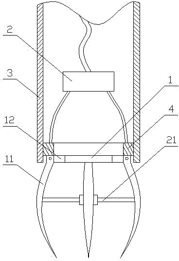
[0028] Extrusion and expansion hole construction equipment, such as figure 1 , 2 , 3, including a steel pipe pile 3, a drill bit 1 and a pressure device 2, the drill bit 1 includes a sheath 12 and an arc-shaped digging claw 11. The arc-shaped digging claws 11 are sleeved on the sheath 12, and are easy to assemble and disassemble, and can be interchanged.

[0029] It also includes a water injection pipeline and a mud pump, the diameter of the drill bit 1 is smaller than the inner diameter of the steel pipe pile 3, the drill bit 1 is connected to the retaining ring 4, and the pressure device 2 is connected to the retaining ring 4. A retaining ring 4 is set between the drill bit 1 and the pressure device 2. The retaining ring 4 carries all the force transmitted by the pressure device 2 and transmits the pressure to the drill bit 1. This design greatly protects the drill bit 1 and improves the performance of the drill bit 1. service life.

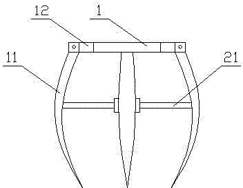
[0030] There are four arc-shaped digg...

Embodiment 2

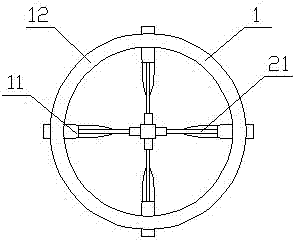
[0041] Extrusion and expansion hole construction equipment, such as figure 1 , 4 , 5, it includes a steel pipe pile 3, a drill bit 1 and a pressure device 2, and the drill bit 1 includes a sheath 12 and an arc-shaped digging claw 11. The arc-shaped digging claws 11 are sleeved on the sheath 12, and are easy to assemble and disassemble, and can be interchanged.

[0042] Preferably, it also includes a water injection pipeline and a mud pump, the diameter of the drill bit 1 is smaller than the inner diameter of the steel pipe pile 3, the drill bit 1 is connected to the retaining ring 4, and the pressure device 2 is connected to the retaining ring 4. A retaining ring 4 is set between the drill bit 1 and the pressure device 2. The retaining ring 4 carries all the force transmitted by the pressure device 2 and transmits the pressure to the drill bit 1. This design greatly protects the drill bit 1 and improves the performance of the drill bit 1. service life.

[0043] There are si...


PUM


Abstract

The invention relates to the field of piling equipment, and discloses a squeezed hole construction equipment and construction process. The squeezed hole construction equipment comprises a steel pipe pile (3), a drill (1) and a pressure device (2), wherein the drill comprises a protecting sleeve (12) and an arched cleoid (11). The construction process mainly comprises the following steps of placing the drill (1), opening the petaloid cleoid (11), driving the drill (1) to drill holes by using a hydraulic device, and taking the drill (1) out of the steel pipe pile (3) after the holes are drilled. By hydraulic hole formation, the invention has the advantages of low energy consumption, low cost, fast process and controllable process. The density among piles is greatly improved so that the friction of the piles is greatly improved, the bearing capability of the piles is also improved and the service life of engineering buildings is simultaneously prolonged.

Description

technical field [0001] The invention relates to the field of piling equipment, in particular to extrusion and expansion hole forming construction equipment and construction technology. Background technique [0002] The current piling field mainly adopts the pile top pressure method for pile driving, and the pile top pressure is mainly divided into two types: static pressure type and drop hammer type. The traditional piling method is easy to cause buckling of steel pipe piles; and the drop hammer piling method not only requires a lot of energy, but also produces very large noise pollution, so it is difficult to carry out construction in urban areas or places with many people. Another method is to use bored pile installation technology. The main steps are to dig a hole first, then put it into the casing, then add water while drilling through the drill bit, and at the same time inject clean water and extract the muddy water and muddy water out of the pipe pile. At the same tim...

Claims


Application Information

Patent Timeline
Patent Type & Authority Patents(China)
IPC IPC(8): E02D7/26
Inventor 逯彦秋李淑琴孙天明
Owner ZHEJIANG CTB WAVEFORM STEEL WEB
Why Eureka
Try Eureka