Electrically-operated servo valve and method for controlling same

A technology of servo controller and electric valve, applied in the direction of valve details, valve devices, engine components, etc., can solve problems such as high cost, high requirements for the use environment of photoelectric encoders, and complex structures

Inactive Publication Date: 2013-01-30
HANGZHOU SES MACHINERY
View PDF2 Cites 0 Cited by
  • Summary
  • Abstract
  • Description
  • Claims
  • Application Information

AI Technical Summary

Problems solved by technology

The document with the application number 200710036766 proposes an improved encoder for electric valves, but the structure is complex, the cost is high, and the photoelectric encoder has high requirements for the use environment

Method used


Image

  • Electrically-operated servo valve and method for controlling same
  • Electrically-operated servo valve and method for controlling same
  • Electrically-operated servo valve and method for controlling same

Examples


Embodiment 1

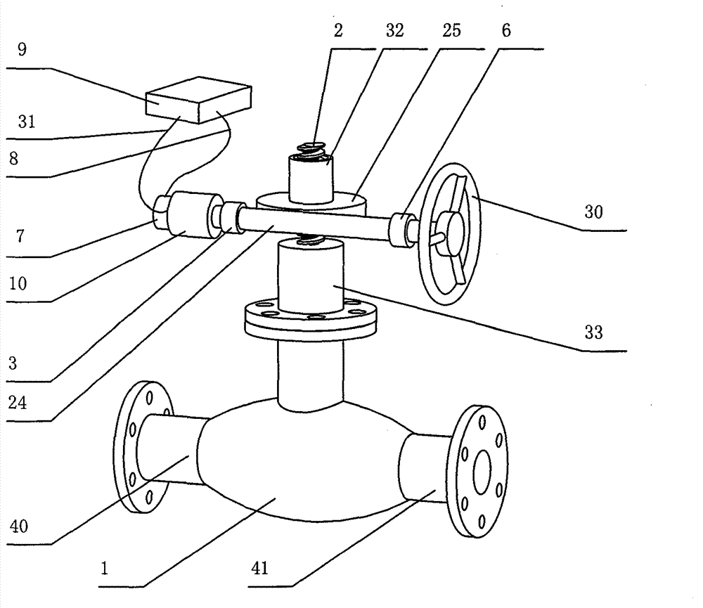
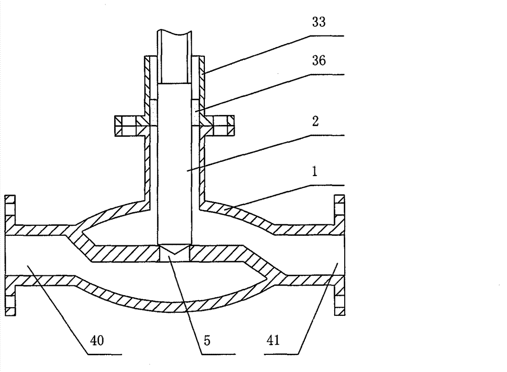
[0135] figure 1 It is a schematic diagram of the overall structure of Embodiment 1 of the servo electric valve of the present invention. Such as figure 1 As shown, the present invention provides a servo electric valve, which includes a valve body 1, and the two ends of the valve body 1 are a liquid outlet chamber 41 and a liquid inlet chamber 40 respectively. The valve body 1 is provided with a valve stem 2, the output of the servo motor 10 is connected to the worm 24 at the input end of the reducer through the coupling 3, the turbine 25 at the output end of the reducer is connected to the valve stem 2, and the valve stem 2 is connected to the valve hole 5 And control the opening of the valve hole 5. The motor shaft of the servo motor 10 is provided with a position detection device 7, and the position detection device 7 inputs signals to the servo controller 9 to control the servo motor 10 to drive the reducer and control the opening of the valve hole 5 through the valve rod...

Embodiment 2

[0153] Figure 7 It is a schematic diagram of the overall structure of Embodiment 2 of the servo electric valve of the present invention. Such as Figure 7 As shown, the turbine shaft 32 is also provided with a position detection device 7, the position detection device 7 detects the angle information of the valve stem 2, and the input signal is sent to the servo controller 9, and the servo controller 9 controls the servo motor 10 to drive the reducer and pass the valve stem. 2 Control the opening of the valve hole 5.

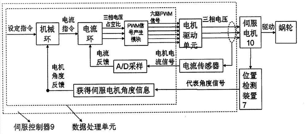
[0154] Figure 8 It is a schematic diagram of the control structure of Embodiment 2 of the servo electric valve of the present invention. Such as Figure 8 As shown, the difference from Embodiment 1 is that a position detection device 7 is respectively installed on the worm 2 and the motor shaft, which are respectively used to detect the angular position of the worm 2 and the angular position of the motor shaft, and transmit them to the servo controller 9 ,...

Embodiment 3

[0157] Figure 9 It is a schematic diagram of the overall structure of Embodiment 3 of the servo electric valve of the present invention. Such as Figure 9 As shown, the difference from the second embodiment is that a transmission mechanism is additionally provided on the valve stem 2, the driving part of the transmission mechanism is arranged on the valve stem 2, and a position detection device 7 is provided on the rotating shaft of the driven part. In this embodiment, the driving part of the transmission mechanism is the gear 43, and the driven part is the gear 44, that is, the gear transmission mechanism. A gear 44 is provided on the gear shaft 42 . The position detection device 7 inputs signals to the servo controller 9, and the servo controller 9 controls the servo motor 10 to drive the reducer and controls the opening of the valve hole 5 through the valve stem 2.

[0158] figure 2 to combine Figure 9 As shown, when the valve stem 2 is at the bottom, the valve hole...


PUM


Abstract

A servo motor operated valve and a control method thereof are disclosed. The servo motor operated valve includes a valve body (1) and a valve rod (2) mounted in the valve body (1), the output end of a servo motor (10) is connected with the input end (24) of a reducer (24, 25) through a coupling (3), and the output end (25) of the reducer (24, 25) is connected with the valve rod (2), the valve rod (2) is connected with a valve opening (5) to control the opening of the valve opening (5). A position detection means (7) is provided on the shaft of the servo motor (10) and inputs a control signal to a servo controller (9) to control the servo motor (10) to drive the reducer (24, 25) and control the opening of the valve opening (5) through the valve rod (2). The control method includes the steps of setting the opening of the valve, calculating the angle of the shaft of the motor, detecting the angle of the shaft of the motor, et al. The invention has high control precision and high reliability, and can control torque and rotation speed.

Description

technical field [0001] The invention relates to an electric valve and its control method, in particular to a servo electric valve which uses a servo motor to control the opening of the valve and its control method. Background technique [0002] Electric valves are widely used in chemical, steel, petroleum and other fields. At present, the motors used for electric valves include asynchronous motors, stepper motors, and inverter-driven motors. The motor is connected to the valve stem through a reducer to control the opening and closing of the valve. [0003] The asynchronous motor is generally used with the limiter at the same time. The control circuit of the motor is opened or cut off through the limit signal of the limiter. This method can only control the full opening or closing of the valve, and the limiter is easy to damage. In addition The torque of the asynchronous motor cannot be controlled, and the torque exceeding the limit may cause damage to the valve or equipment...

Claims


Application Information

Patent Timeline
Patent Type & Authority Patents(China)
IPC IPC(8): F16K31/04
CPCF16K31/046
Inventor 郝双晖郝明晖
Owner HANGZHOU SES MACHINERY
Why Eureka
Try Eureka