Ultrasonic reactor based on diffuse sound field

An ultrasonic reactor and diffused sound field technology, applied in the chemical/physical/physical chemical process of applying energy, etc., can solve the problems of uneven sound treatment and low utilization rate of sound energy.

Inactive Publication Date: 2010-11-10
NANJING UNIV OF AERONAUTICS & ASTRONAUTICS
View PDF5 Cites 15 Cited by
  • Summary
  • Abstract
  • Description
  • Claims
  • Application Information

AI Technical Summary

Problems solved by technology

[0003] In order to overcome the problems of uneven sonication and low utilization rate of sound energy in existing ultrasonic reactors, the patent of the present invention provides a novel ultrasonic reactor,...

Method used


Image

  • Ultrasonic reactor based on diffuse sound field
  • Ultrasonic reactor based on diffuse sound field
  • Ultrasonic reactor based on diffuse sound field

Examples


Embodiment 1

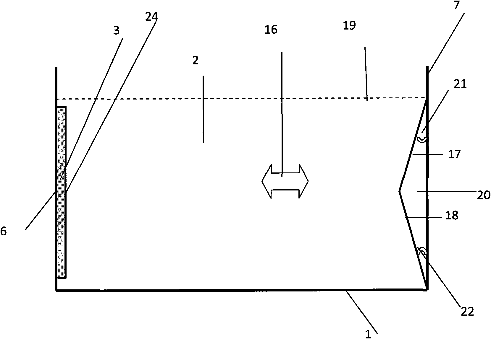
[0019] The ultrasonic reactor of Embodiment 1 is shown in FIG. 1 .

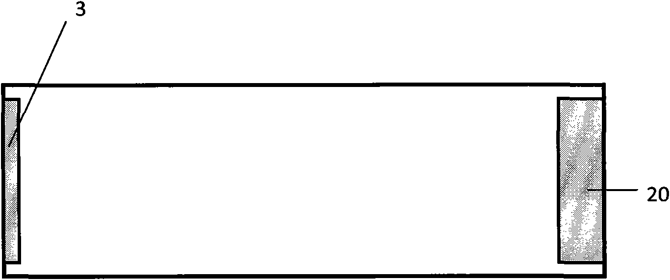
[0020] The ultrasonic reactor rectangular metal box 1 with a submerged flat-plate ultrasonic transducer is equipped with treated water 2 . The ultrasonic transducer 3 (the embodiment adopts an immersion-type flat-panel ultrasonic transducer) is fixed on the first wall 6 . On the second wall 7 facing the first wall 6 there is an acoustic reflector 20 with two acoustic reflection planes 17 and 18 . The two sound reflection planes 17 and 18 are not perpendicular to the incident sound waves from the ultrasonic transducer 3 . A diffuse ultrasonic field 16 is formed in the treated liquid by means of many reflections from the acoustically reflecting planes 17 and 18, the tank 1, the liquid surface 19 and the transducer radiating surface 24.

[0021] The inner dimension of the rectangular metal box 1 is 33.88cm (length) × 26cm (width) × 36cm (height). The height of the water in the box is 31 cm. The size of the i...

Embodiment 2

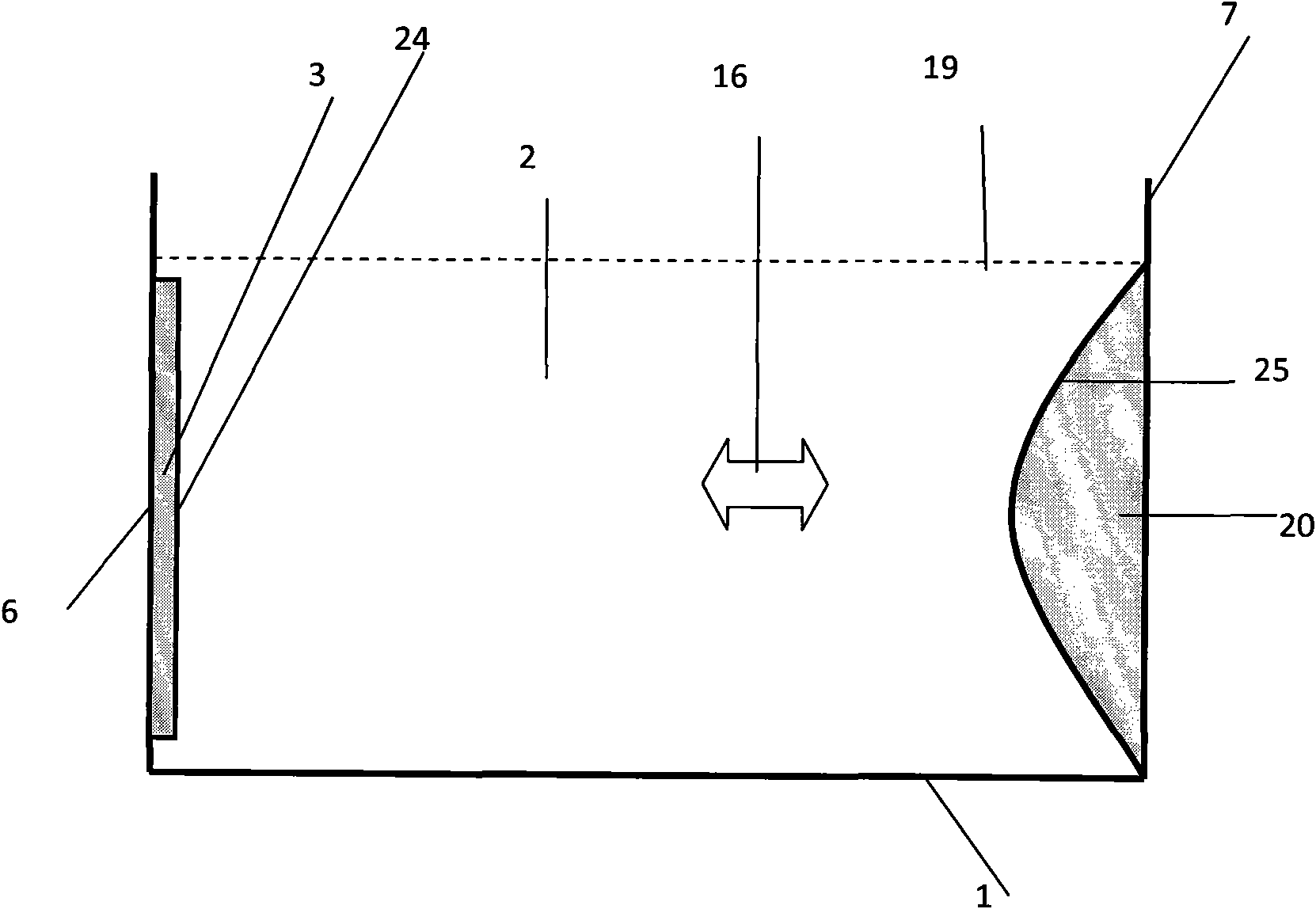
[0023] The ultrasonic reactor of Example 2 is shown in FIG. 2 .

[0024] The ultrasonic reactor rectangular metal box 1 with a submerged flat-plate ultrasonic transducer is equipped with treated water 2 . The ultrasonic transducer 3 (the embodiment adopts an immersion-type flat-panel ultrasonic transducer) is fixed on the first wall 6 . On the second wall 7 facing the first wall 6, an acoustic reflector 20 having a cylindrical sound reflecting surface 25 is provided. The cylindrical sound reflecting surface 25 is not perpendicular to the incident sound wave from the ultrasonic transducer 3 . By virtue of the multiple reflections of the cylindrical acoustic reflection surface 25, the tank 1, the liquid surface 19) and the transducer radiation surface 24, a diffuse ultrasonic field 16 will be formed in the treated liquid.

[0025] The inner dimension of the rectangular metal box 1 is 33.88cm (length) × 26cm (width) × 36cm (height). The height of the water in the box is 31 cm....


PUM


Abstract

The invention relates to an ultrasonic reactor based on a diffuse sound field, in particular to a device for treating liquid by utilizing an ultrasonic cavitation effect. The ultrasonic reactor comprises a tank body (1), an ultrasonic transducer (3) and a sound reflector (20), wherein the tank body (1) is used for containing liquid to be treated; the ultrasonic transducer (3) is installed in the tank body; and the sound reflector (20) is positioned on the wall surface of the tank body opposite to the radiating surface (24) of the ultrasonic transducer (3) and is provided with a sound reflecting surface which is not perpendicular to influent sound waves emitted by the ultrasonic transducer (3). The ultrasonic reactor carries out sound treatment to the liquid in the ultrasonic reactor by utilizing a uniform ultrasonic field to realize the uniform sound treatment of the ultrasonic reactor and improve the utilization ratio of sound energy in the ultrasonic reactor.

Description

technical field [0001] The ultrasonic reactor based on the diffusion sound field in the present invention relates to a device for treating liquid by using ultrasonic cavitation effect. Background technique [0002] The ultrasonic reactor uses the local high temperature and high pressure (~5000K, ~2000atm) generated by the ultrasonic cavitation effect to treat liquids such as water. A traditional ultrasonic reactor system structurally includes a tank, a liquid to be treated in the tank, an ultrasonic transducer for applying ultrasonic waves to the liquid to be processed, and a drive circuit for the ultrasonic transducer. It is used in disinfection and sterilization of drinking water, decomposition of carcinogens in drinking water, disinfection and sterilization of wastewater, decomposition of organic matter in wastewater, physical catalysis of chemical synthesis and crystallization process, acceleration of fermentation process, production of biomass gas and liquid fuel, etc. ...

Claims


Application Information

Patent Timeline
IPC IPC(8): B01J19/10
Inventor 胡俊辉杨颖姚志远赵淳生
Owner NANJING UNIV OF AERONAUTICS & ASTRONAUTICS
Why Eureka
Try Eureka