Pumping system and concrete pump truck having the same

A pumping system and pumping technology, which are applied in the pumping, construction material processing, construction and other directions, can solve the problems of occupying the storage space of the hopper 110, affecting the suction performance of the concrete pump, hindering the flow of concrete mud, etc., so as to improve the suction performance effect

Active Publication Date: 2010-11-10
SANY AUTOMOBILE MFG CO LTD
View PDF6 Cites 6 Cited by
  • Summary
  • Abstract
  • Description
  • Claims
  • Application Information

AI Technical Summary

Problems solved by technology

[0005] In the prior art, the left feeding hole and the right feeding hole on the rear wallboard 112 are arranged horizontally respectively, and their centerlines basically coincide with the axis of the corresponding delivery cylinder; when the delivery cylinder is sucking material, the concrete slurry is mainly The delivery cylinder enters the delivery cylinder under the action of suction; therefore, the concrete pump cannot use the self-flowing performance of the concrete mud, and its suction performance is difficult to meet the needs of actual operations, which in turn adversely affects the pumping efficiency of the concrete pump
[0006] In addition, the reversing mechanism 130 is connected to the input end of the S-shaped elbow 120 and is located above the input end of the S-shaped elbow 120, occupying a part of the accommodation space of the hopper 110, resulting in a reduction in the available volume of the hopper 110; in addition, The reversing mechanism 130 will also hinder the flow of concrete slurry, which is not conducive to the suction of concrete slurry, and further affects the suction performance of the concrete pump

Method used


Image

  • Pumping system and concrete pump truck having the same
  • Pumping system and concrete pump truck having the same
  • Pumping system and concrete pump truck having the same

Examples


Embodiment Construction

[0052] The present invention will be described in detail below in conjunction with the accompanying drawings. The description in this part is only exemplary and explanatory, and should not have any limiting effect on the protection scope of the present invention. The present invention will be described below with concrete pump as an example. It should be clearly stated that the technical solutions provided by the present invention can also be applied to pumping systems for pumping mud or other viscous materials with the same performance as concrete mud.

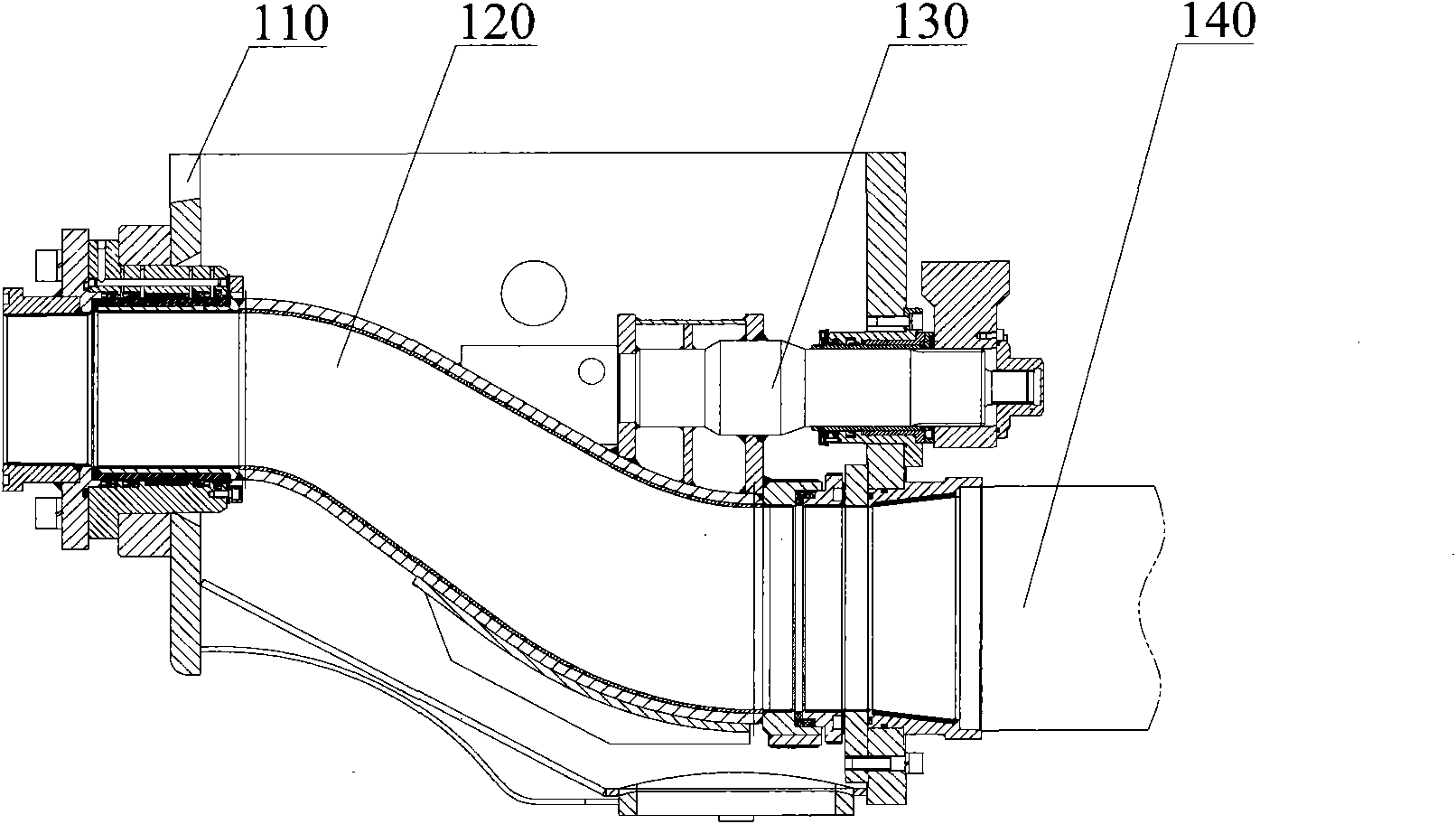
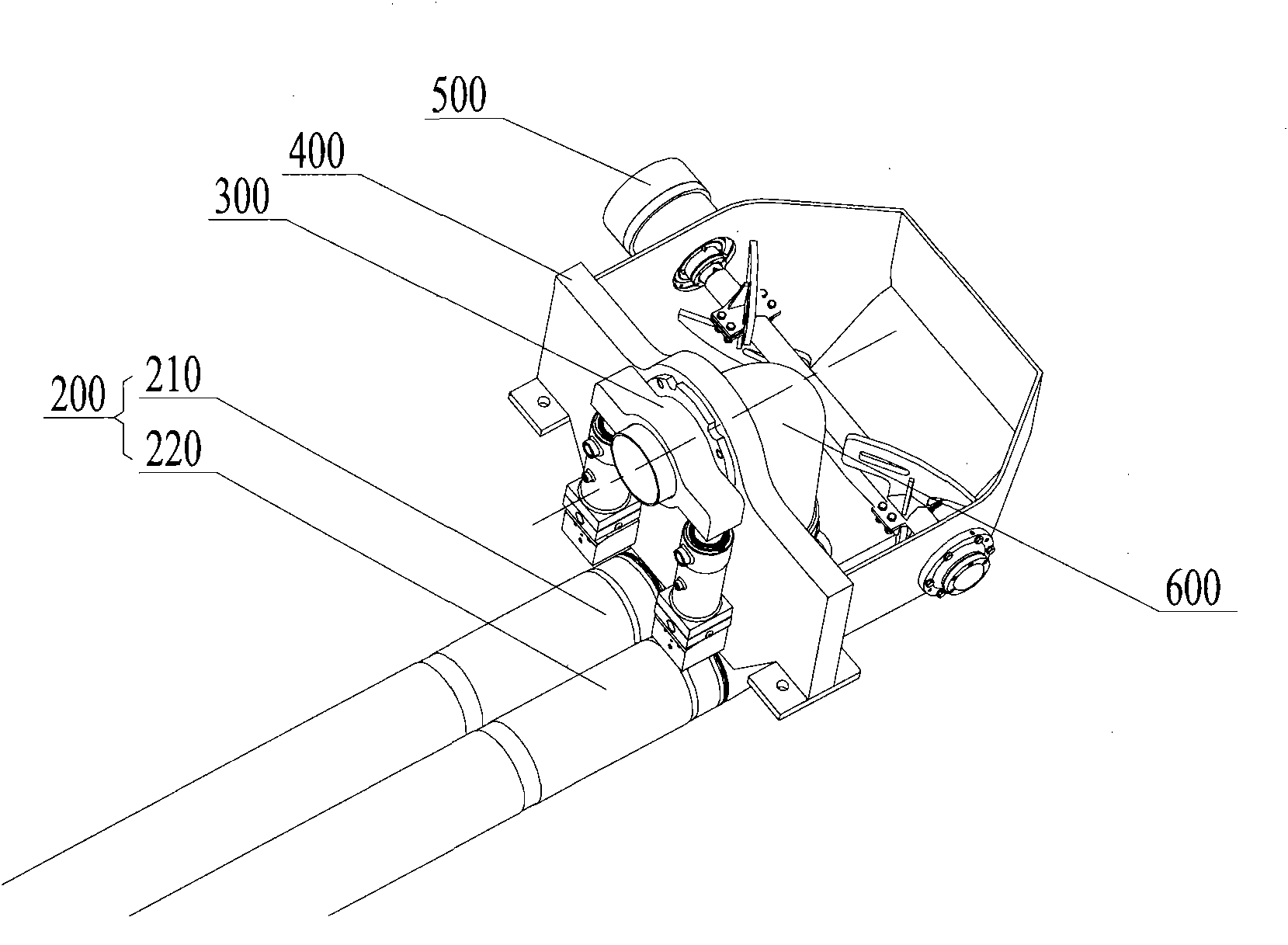
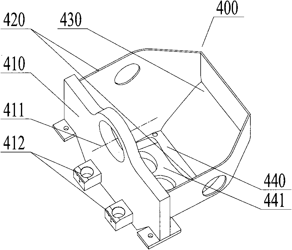
[0053] Please refer to figure 2 , which is a schematic diagram of the assembly structure of the concrete pump provided in Embodiment 1. The concrete pump provided in Embodiment 1 includes a hopper 400 , a stirring mechanism 500 , a distribution valve 600 , a swing valve mechanism 300 and a pumping power mechanism 200 . The hopper 400 is used to accommodate a predetermined amount of concrete slurry, and the stirring mechanis...


PUM


Abstract

The invention discloses a pumping system and a concrete pump truck. The pumping system comprises a pumping power mechanism, a hopper and a distribution valve, wherein the distribution valve comprises a first tube section and a second tube section, the central line of the second tube section is vertical to that of the first tube section, and the first tube section can be mounted on the hopper in a rotation way; the lower end surface of the second tube section is matched with a sealing surface of a bottom wall board of the hopper, and the bottom wall board is provided with a delivery hole; and on a first position, the second tube section is communicated with a delivery cylinder of the pumping power mechanism through a delivery hole, and on a second position, the delivery cylinder is communicated with an accommodating space of the hopper through the delivery hole. In the disclosed pumping system and the concrete pump truck, dope inside the hopper can automatically flow into the first delivery cylinder through the delivery hole under the gravity effect, so the delivery cylinder can smoothly absorb the dope of a pre-determined quantity; therefore, the self flowing performance of the dope can be adequately utilized to improve the absorption performance of the pumping system.

Description

technical field [0001] The invention relates to the technology for pumping viscous materials such as concrete mud, in particular to a pumping system and a specific concrete pump truck for the pumping system. Background technique [0002] Concrete pump is one of the most widely used concrete machines at present, which is used to send concrete slurry to the predetermined working position for concrete pouring operation. The distribution valve is a key component of the concrete pump. At present, in the domestic and foreign markets, the distribution valve of the concrete pump is mainly an S-type distribution valve, and the S-type distribution valve mainly includes an S-shaped elbow. [0003] Please refer to figure 1 , figure 1 It is a structural schematic diagram of a concrete pump with an S-shaped distribution valve in the prior art. The concrete pump includes a hopper 110 , an S-shaped elbow 120 , a driving mechanism 130 and two delivery cylinders 140 . The hopper 110 is su...

Claims


Application Information

Patent Timeline
Patent Type & Authority Applications(China)
IPC IPC(8): F04B15/02E04G21/02
Inventor 易小刚董旭辉汤如龙张春光
Owner SANY AUTOMOBILE MFG CO LTD
Why Eureka
Try Eureka