Method and device for improving supply voltage at tail end of long supply arm of heavy haul railway

A technology of power supply arm and railway, applied in the direction of harmonic reduction device, AC network voltage adjustment, flexible AC transmission system, etc., to achieve the effect of reducing negative sequence current

Active Publication Date: 2010-11-10
ZHUZHOU NAT ENG RES CENT OF CONVERTERS
View PDF0 Cites 15 Cited by
  • Summary
  • Abstract
  • Description
  • Claims
  • Application Information

AI Technical Summary

Problems solved by technology

[0011] The problem to be solved by the invention of this patent is: aiming at the deficiency of the voltage loss control method of the end network voltage AT power supply mode of the long power supply arm of the heavy-duty railway, a method that can effectively...

Method used


Image

  • Method and device for improving supply voltage at tail end of long supply arm of heavy haul railway
  • Method and device for improving supply voltage at tail end of long supply arm of heavy haul railway
  • Method and device for improving supply voltage at tail end of long supply arm of heavy haul railway

Examples


Embodiment 1

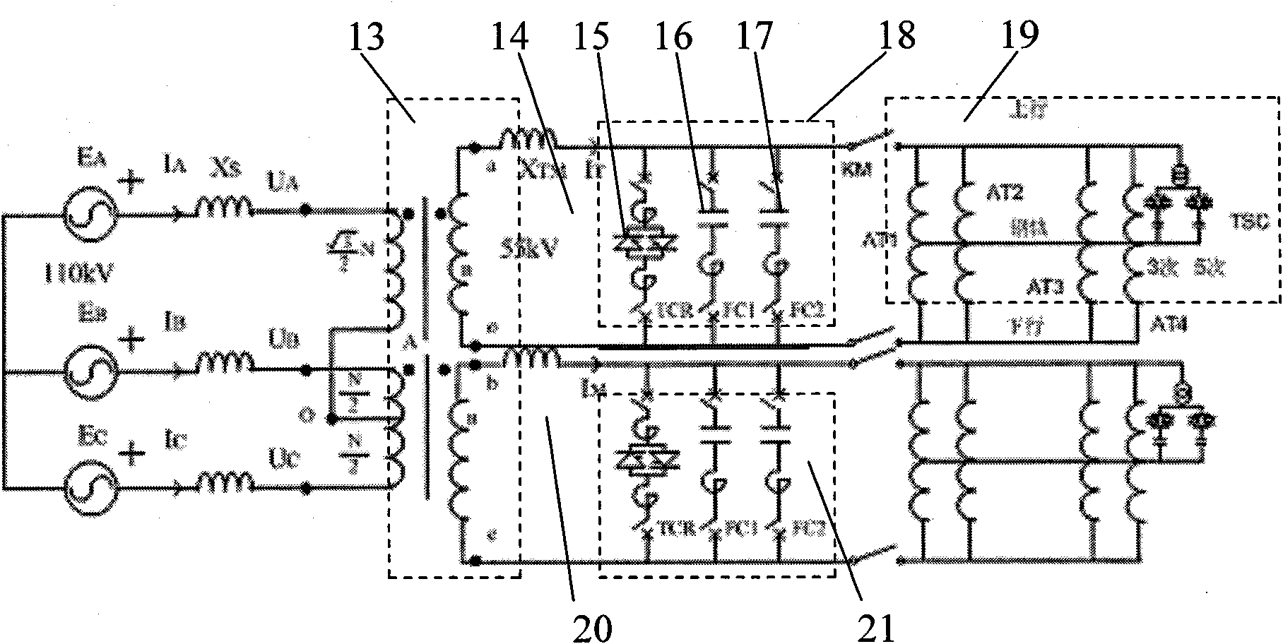
[0027] A device for increasing the network voltage at the end of a power supply arm in a heavy-duty railway AT power supply system. A SCOTT transformer 1 is provided in the heavy-duty railway AT power supply system. T block 14 and M block 20 are equipped with a set of SVC devices 18 and 21 composed of a TCR branch 15, FC1 capacitor branch 16, and FC2 capacitor branch 17 respectively, wherein FC1 capacitor branch 16 and FC2 capacitor branch 17 are exactly the same, which can ensure that the entire SVC device can be derated for compensation when a set is overhauled. At the same time, a step-down TSC group 19 is installed on the uplink, and the step-down TSC group 19 is respectively set as 3rd and 5th filter branches. Among them, the up line is a heavy-duty climbing line, and the down line is a downhill line, so the compensation on the up line can reduce the current flowing through the AT, and the filtering effect is good. circuit such as figure 1 As shown, where KM is the load...


PUM


Abstract

The invention relates to a method and a device for improving supply voltage at the tail end of a long supply arm of a heavy haul railway. The method is characterized in that: a direct hanging thyristor controlled reactor (TCR)-type static var compensator (SVC) is arranged at the outlet end of a Scott main transformer; a plurality of groups of step-down thyristor switched capacitors (TSCs) are arranged at an autotransformer (AT) end at the tail end of the long supply arm at the same time; and the tail end of the supply arm is compensated by using a step-down TSC grouping mode so as to improve the supply voltage at the tail end. The Scott transformer is arranged in a power supply system of the AT of the heavy haul railway and is provided with a T seat outlet end and an M seat outlet end; the T seat and M seat outlet ends of the Scott transformer are provided with a set of SVC devices consisting of a TCR branch and two fixed capacitor branches FC1 and FC2, wherein FC1 is identical to the FC2, so that the whole SVC can be subjected to derating compensation when the set of devices are maintained; and simultaneously, the step-down TSC groups are arranged in uplink, respectively set as three-time and five-time filter branches, wherein the uplink is a heavy climbing line, and downlink is a descending line.

Description

technical field [0001] The invention relates to a power transmission method and device, in particular to a method and device for increasing network voltage at the end of a long power supply arm of a heavy-duty railway. The international patent classification number is B61F05 / 02, which is mainly used for power transmission and distribution of heavy-duty rail transit system. Background technique [0002] With the rapid development of my country's national economy, higher requirements are placed on the railway transportation capacity, which also makes the traction load of electrified railways continue to increase. For many lines, the voltage level of the traction network is too low under heavy load conditions, which affects the normal traction operation of trains and limits the further growth of traffic volume. [0003] In the traction network, the parallel autotransformer forms the AT power supply mode, which has the characteristics of less voltage and power loss and longer p...

Claims


Application Information

Patent Timeline
IPC IPC(8): H02J3/16H02J3/01
CPCY02E40/34Y02E40/12Y02E40/10Y02E40/30Y02E40/40
Inventor 王卫安张定华谭胜武马雅青周方圆黄燕艳杨磊张斌胡前王小方李军邓建华
Owner ZHUZHOU NAT ENG RES CENT OF CONVERTERS
Why Eureka
Try Eureka