
Storage battery charging and discharging device

A charging and discharging device and storage battery technology, applied in the direction of battery circuit devices, circuit devices, collectors, etc., can solve the problems of not meeting the development requirements, not fully utilizing energy, etc., to save discharge resistors, avoid damage to thyristors, and output voltage wide range of effects

Inactive Publication Date: 2012-11-28
湖北德普电气股份有限公司
View PDF0 Cites 0 Cited by
  • Summary
  • Abstract
  • Description
  • Claims
  • Application Information

AI Technical Summary

Problems solved by technology

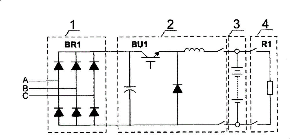
Among them, the AC voltage becomes a fixed DC voltage after rectification, and then the DC chopper unit adjusts the output DC voltage to charge the battery. When the battery is discharged, it is completed through another discharge resistor. This method is superior to the input power factor index. In the form of thyristor phase-controlled rectification, the energy is consumed by the resistor when the battery is discharged, the control is simple, and there is no problem of inverter failure caused by the sudden drop of the power grid during discharge, but a large discharge resistor is required during discharge, and the energy is not fully utilized
[0005] Therefore, the existing technical route can no longer meet the development requirements, and new solutions need to be actively sought

Method used

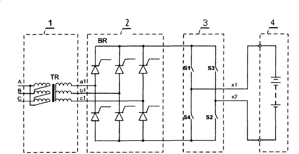

Image

  • Storage battery charging and discharging device
  • Storage battery charging and discharging device
  • Storage battery charging and discharging device

Examples


Embodiment Construction

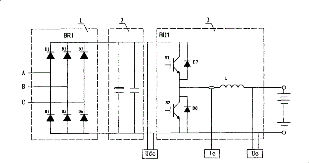
[0021] Such as image 3 As shown, 1 is an uncontrolled rectifier unit, 2 is a DC link filter unit, and 3 is a DC-DC bidirectional chopper unit, which constitutes a battery charging and discharging component. The uncontrolled rectifier unit 1, the DC link filter unit 2 and the DC-DC bidirectional chopper unit 3 are connected in series. The diodes D7 and D8 are the anti-parallel diodes of the power switch tubes S1 and S2. The input terminal is an AC voltage source, and the output terminal is connected to a battery Load, the detection unit detects the DC bus voltage, output voltage and output current respectively.

[0022] When the battery charging and discharging device is in the charging state, the switch S1, the diode D8 and the inductor L form a BUCK (chopping) circuit to provide an adjustable DC output current for the load.

[0023] When the battery charging and discharging device is in the discharging state, the switch tube S2, the diode D7 and the inductor L form a BOOST (boost...


PUM


Abstract

The invention provides a storage battery charging and discharging device, which is used for the production and test of the charging and discharging of storage batteries. The storage battery charging and discharging device comprises a storage battery charging and discharging assembly and a full digital controller, wherein a main circuit consists of a non-controlled rectification unit, a DC wave filtering unit and a DC-DC two-way wave chopping unit through serial connection, the non-controlled rectification unit consists of a diode rectification bridge, the DC wave filtering unit consists of a DC wave filtering capacitor and a high-frequency absorption capacitor through parallel connection, the two-way wave chopping unit consists of a power switch device and a DC output inductor, and the full digital controller uses a high-performance digital signal microprocessor as a core for generating pulse width modulation signal control signals for carrying out dynamic control on the DC output voltage and current. The invention avoids the defects of the charging and discharging device in aspects of power factors and energy utilization, the electric energy can be efficiently utilized, the modularized combination, the charging and discharging energy two-way flowing function and the safety power failure machine halt function can be realized, and the invention has the advantages of high universality, high network side power factor, wide range of output voltage, high dynamic precision of output current and high response speed.

Description

Technical field [0001] The present invention relates to a battery charging and discharging power supply in the technical field of power electronic conversion, in particular to a structure in which an uncontrolled rectifier unit and a DC-DC chopper-boost bidirectional conversion unit are connected in series, and the output voltage and current adopt dynamic The control, power supply and load have a battery charging and discharging device with bidirectional energy flow. Background technique [0002] As a reliable chemical power source, storage batteries are widely used in power systems, transportation, portable electronic products and other industrial fields. Especially in sectors such as national defense, telecommunications and finance, storage batteries are one of the key components in these systems as the backup power source of the system. With the development of economy, the use of batteries has increased year by year in recent years, which has put forward higher requirements o...

Claims


Application Information

Patent Timeline
Patent Type & Authority Patents(China)
IPC IPC(8): H02J7/02
CPCY02P70/10
Inventor 王国安刘士杰陈畅李明勇匡鹏朱录涛李妙弦
Owner 湖北德普电气股份有限公司
Learn More