Lighting apparatus

A technology for lighting devices and control devices, which is applied to lighting devices, fixed lighting devices, components of lighting devices, etc., and can solve problems such as the inability to suppress the amount of light, the lack of room illumination, and the inability to use multiple types of lighting.

Inactive Publication Date: 2010-11-10
SHARP KK
View PDF6 Cites 21 Cited by
  • Summary
  • Abstract
  • Description
  • Claims
  • Application Information

AI Technical Summary

Problems solved by technology

[0008] In the lighting device disclosed in Patent Document 1, when a narrow-angle light source is turned on, although a narrow area directly under the light source is illuminated, since the surrounding area is in a dim state, the amount of light entering human eyes can be suppressed. On the other hand, the entire Insufficient lighting in the room
In the case of lighting the light source for peripheral lighting, the entire room can be illuminated, but the amount of light that enters the human eye cannot be suppressed because the light is irradiated in multiple directions
Therefore, the lighting device disclosed in Patent Document 1 has a problem that it cannot properly perform various types of lighting according to the time or the living conditions of the user.

Method used


Image

  • Lighting apparatus
  • Lighting apparatus
  • Lighting apparatus

Examples


no. 1 approach

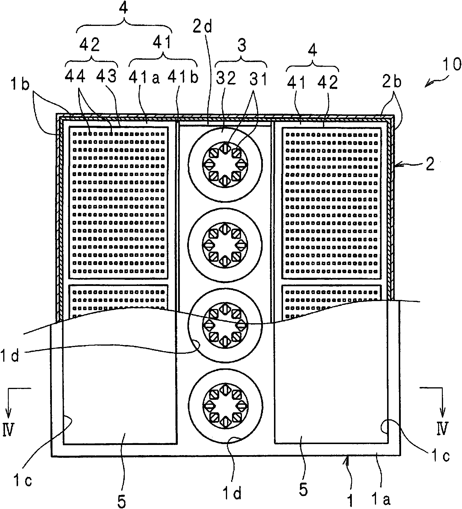
[0068] image 3 is a schematic top view of the lighting device 10 according to the first embodiment of the present invention, Figure 4 is along image 3 Schematic cross-sectional view of line IV-IV. and, image 3 Indicates that a part of the lighting device 10 is placed along the Figure 4 Partial sectional view taken along line III-III.

[0069] In the figure, the cover 1 is made of resin or metal, and the cover 1 includes: a rectangular plate portion 1a; and rectangular four side walls 1b, 1b, . . . Extends in a generally vertical direction. On the plate portion 1a, two rectangular windows 1c, 1c are formed along opposite sides. Further, between the two rectangular windows 1c, 1c of the plate portion 1a, a plurality of (four in the figure) circular windows 1d, 1d... are formed at equal intervals along the rectangular windows 1c, 1c. A metal frame 2 is fitted on the cover 1 , and the cover 1 and the frame 2 constitute a housing of the lighting device 10 .

[0070] Th...

no. 2 approach

[0101] Figure 10 It is another example of a flowchart showing the lighting control processing procedure of the lighting device 10 . Since other structures are the same as those described in the first embodiment, drawings and descriptions are omitted.

[0102] After power-on, the processing unit 61b judges whether the control unit 61 is in the lighting command (step S11).

[0103] In step S11, when it is judged that the lighting command is in progress (step S11: YES), the time is read from the clock part 61c into the processing part 61b (step S12).

[0104] On the other hand, in step S11, when it is judged that there is no lighting instruction (step S11: No), the first light emitting parts 3, 3... and the second light emitting parts 4, 4 are kept in the state of being turned off Next, the lighting control operation of the lighting device 10 is ended (step S13).

[0105] Next, the control unit 61 reads the setting values ​​of the first light emitting units 3, 3... and the se...

no. 3 approach

[0109] Figure 12 It is another example of a flowchart showing the lighting control processing procedure of the lighting device 10 . Since other structures are the same as those described in the first embodiment, drawings and descriptions are omitted.

[0110] After power-on, the processing unit 61b judges whether the control unit 61 is in the lighting instruction (step S21).

[0111] In step S21, when it is determined that the lighting command is in progress (step S21: YES), the time is read from the clock part 61c into the processing part 61b (step S22).

[0112] On the other hand, in step S21, when it is judged that there is no lighting instruction (step S21: No), the first light-emitting parts 3, 3... and the second light-emitting parts 4, 4 are kept off. Next, the lighting control operation of the lighting device 10 is ended (step S23).

[0113] Next, the control unit 61 reads the setting values ​​of the first light emitting units 3, 3... and the second light emitting un...


PUM


Abstract

A lighting apparatus enabling lighting adequate for time or the lifestyle of the user by regulating the intensity of light in the wavelength region leading to reduction of melatonin secretion and emitted from a luminous portion of the lighting apparatus toward the eyes of the user and thereby varying the influence of the light on melatonin secretion reduction. First and second luminous portions (3, 3, ..., 4, 4, ...) having different luminous intensity distribution characteristics are used in the lighting apparatus. A control section of the lighting apparatus controls the luminous intensitiesof the first and second luminous portions (3, 3, ..., 4, 4, ...) so as to vary the intensity of light in the wavelength region reducing the melatonin secretion and emitted in a predetermined direction. Consequently, the intensity of light emitted toward the eyes of the human (in the predetermined direction) in a normal usage mode is varied, and thus the intensity of light in the wavelength regionentering the eyes of the human and reducing the melatonin secretion is regulated. With this, the influence on the melatonin secretion reduction can be varied, and lighting adequate for time or the lifestyle of the user is achieved.

Description

technical field [0001] The present invention relates to a lighting device that adjusts the amount of light of a wavelength that suppresses secretion of melatonin irradiated from a light emitting unit in a predetermined direction. Background technique [0002] In recent years, lighting devices having light emitting units of various light sources including incandescent lamps, low-voltage discharge fluorescent lamps, fluorescent lamps, light emitting diodes (hereinafter referred to as LEDs) and the like have been used as lighting devices. [0003] It is well known that at night, especially before going to bed, a light source that emits light with a low color temperature such as an incandescent lamp is used to illuminate the interior of a house, and a light source that emits light with a high color temperature such as white or daylight is used for lighting. It can promote a smooth sleep compared with the situation in the normal situation. This is because the secretion of melato...

Claims


Application Information

Patent Timeline
Patent Type & Authority Applications(China)
IPC IPC(8): H05B37/02F21S8/02F21S8/04F21Y101/02
CPCA61N5/0618A61N2005/0634F21S8/04F21V14/08F21V23/0457A61N2005/0663Y02B20/42F21V14/02H05B33/0863F21V23/0442Y02B20/46H05B37/0218H05B37/0281F21Y2101/02F21S8/02F21V19/02F21Y2113/00F21Y2105/10F21Y2115/10H05B45/20H05B47/11H05B47/16Y02B20/40
Inventor 尾山和也
Owner SHARP KK
Why Eureka
Try Eureka