Vibration damper assembly
A shock absorber and assembly technology, applied in the direction of spring/shock absorber, vibration suppression adjustment, mechanical equipment, etc., can solve the problem of not meeting the vibration reduction requirements of the crankshaft system, and achieve the effect of reducing the working frequency
- Summary
- Abstract
- Description
- Claims
- Application Information
AI Technical Summary
Problems solved by technology
Method used
Image
Examples
Embodiment 1
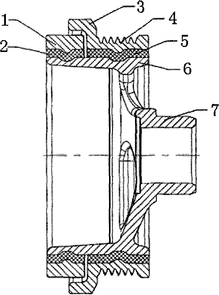
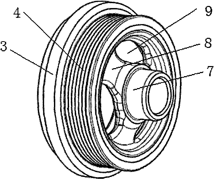
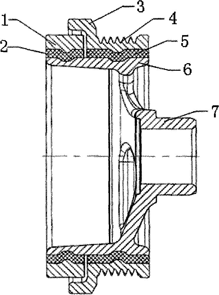
[0017] Example 1, such as figure 1 As shown, a shock absorber assembly includes a shock absorber mounting shaft 7, a spoke 8 and a hub 6, and a pulley 4 acting as an inertia disk is set outside the hub 6 through a second-stage rubber ring 5. On the pulley 4 Set the second stage inertia ring 3. The front end of the hub 6 is also provided with a first-stage rubber ring 2 and a first-stage inertia ring 1 in parallel. The pulley 4 , the second-stage inertia ring 3 and the first-stage inertia ring 1 can rotate mutually between the hub 6 .
Embodiment 2
[0018] Embodiment 2, the second-stage inertia ring 3 and the pulley 4 are integral. All the other are with embodiment 1.
Embodiment 3
[0019] Embodiment 3, in order to optimize the structure and reduce weight, the spokes are trapezoidal and have weight reducing holes on them. There are three lightening holes, which are evenly distributed in the circumferential direction of the spokes. All the other are with embodiment 1 or 2.
PUM
 Abstract
Description
Claims
Application Information
 - R&D
- Intellectual Property
- Life Sciences
- Materials
- Tech Scout
- Unparalleled Data Quality
- Higher Quality Content
- 60% Fewer Hallucinations
Browse by: Latest US Patents, China's latest patents, Technical Efficacy Thesaurus, Application Domain, Technology Topic, Popular Technical Reports.
© 2025 PatSnap. All rights reserved.Legal|Privacy policy|Modern Slavery Act Transparency Statement|Sitemap|About US| Contact US: help@patsnap.com


