Infrared signal transmission circuit of remote controller

An infrared signal and transmitting circuit technology, applied in signal transmission systems, non-electrical signal transmission systems, instruments, etc., can solve problems such as low circuit utilization, save costs, reduce components, and improve accuracy.

Active Publication Date: 2010-11-17
SUZHOU INOSA UNITED POWER SYST CO LTD
View PDF0 Cites 4 Cited by
  • Summary
  • Abstract
  • Description
  • Claims
  • Application Information

AI Technical Summary

Problems solved by technology

[0005] The technical problem to be solved by the present invention is to provide an infrared signal transmitting circuit for the problem of low circuit utilization in the above-mentioned infrared remote control modulation circuit

Method used


Image

  • Infrared signal transmission circuit of remote controller
  • Infrared signal transmission circuit of remote controller
  • Infrared signal transmission circuit of remote controller

Examples


Embodiment Construction

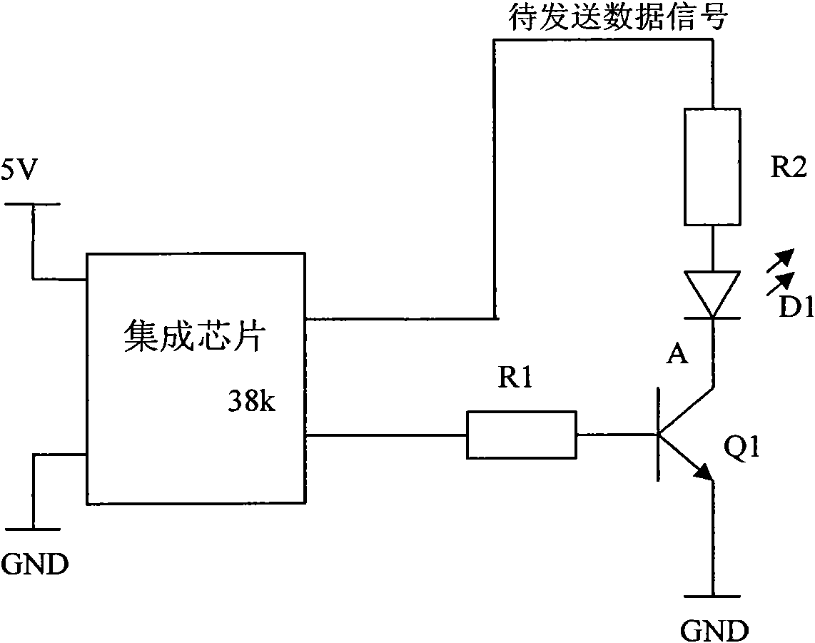
[0022] The invention uses an NPN triode to realize signal modulation and signal amplification at the same time, thereby reducing the components and parts of the infrared signal transmitting circuit of the remote controller.

[0023] Such as image 3 Shown is a circuit diagram of an embodiment of the remote control infrared signal transmitting circuit of the present invention. In this embodiment, the circuit is formed by connecting an integrated chip, an NPN transistor Q1, an infrared emitting diode D1, and two resistors R1 and R2, wherein the collector of the NPN transistor Q1 is connected to the negative pole and the base of the infrared emitting diode D1. The electrode is connected to the carrier signal output port of the integrated chip through the current limiting resistor R1, the emitter is grounded, and the anode of the infrared emitting diode D1 is connected to the output port of the data signal to be sent (URAT port) through the resistor R2.

[0024] The integrated ch...


PUM


Abstract

The invention relates to an infrared signal transmission circuit of a remote controller, which comprises an NPN type triode, wherein the collector of the NPY type triode is connected to the cathode of an infrared transmission diode; the base of the NPN type triode is connected to a carrier signal wire, while an emitter is grounded; and the anode of the infrared transmission diode is connected to a signal wire for data to be transmitted. As signal modulation and signal amplification are simultaneously realized by the NPN type triode and components are reduced, the infrared signal transmission circuit and a debugging process are simplified, and the cost is saved. In addition, the infrared signal transmission circuit generates carrier signals and signals with the data to be transmitted by the same integrated chip, so the carrier signals and the signals with the data to be transmitted are not constructed by separate elements, and the accuracy is improved.

Description

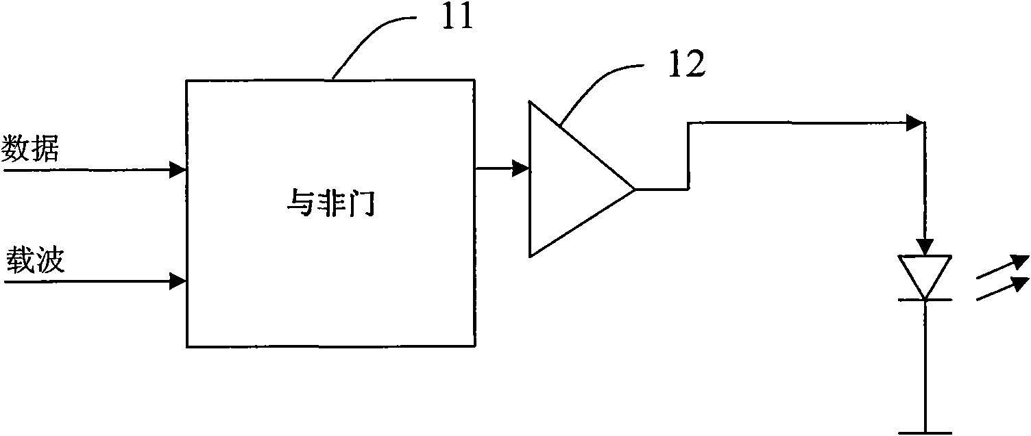
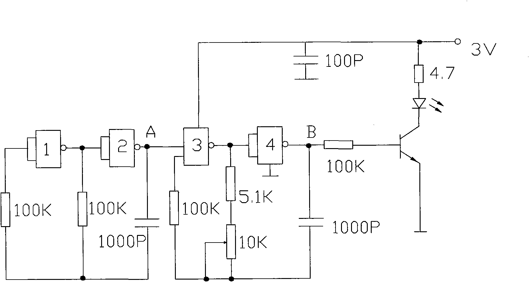
technical field [0001] The invention relates to an infrared remote control device, in particular to a remote control infrared signal transmitting circuit. Background technique [0002] Such as figure 1 As shown, the traditional infrared remote control modulation circuit first loads the data to be sent to a carrier with a certain frequency through a specific circuit 11 (such as a NAND gate) to generate a modulation signal, and then amplifies the above modulation signal through an amplifier 12. Infrared ray emitting diodes are sent out, thereby realizing infrared ray remote control emission. In infrared communication, its carrier frequency is usually 38kHz, and some systems use carrier frequencies such as 32KHz, 36KHz, 40KHz, and 56KHz. [0003] Such as figure 2 Shown is a typical single-channel infrared remote control transmitter circuit. A high-speed CMOS quadruple input NAND gate 74HC00 is used in the transmitting circuit. Among them, "NAND" gates 3 and 4 form a carri...

Claims


Application Information

Patent Timeline
IPC IPC(8): G08C23/04H04B10/04
Inventor 张强何承曾
Owner SUZHOU INOSA UNITED POWER SYST CO LTD
Why Eureka
Try Eureka