
Energy storage method for double-feed current transformer

A technology of doubly-fed converters and energy storage methods, applied in the field of power systems, can solve problems such as grid voltage stability deterioration, failure to recycle, system transient impact, etc., to improve the difficulty of grid connection, improve safety and reliability Performance, power quality improvement effect

Inactive Publication Date: 2010-11-17
SHENZHEN CLOU ELECTRONICS
View PDF0 Cites 17 Cited by
  • Summary
  • Abstract
  • Description
  • Claims
  • Application Information

AI Technical Summary

Problems solved by technology

The rotor short-circuit protection technology using the Crowbar circuit has some disadvantages: First, it needs to add a new protection device, which increases the system cost; in addition, when the power grid fails, although the excitation converter and the rotor The unit operating in motor mode will absorb a large amount of reactive power from the system, which will lead to further deterioration of the grid voltage stability, and the switching operation of the traditional crowbar protection circuit will have a transient impact on the system; finally, the protection device is The electric energy generated by the wind during the failure period is burned with resistors for nothing, and cannot be recycled

Method used


Image

  • Energy storage method for double-feed current transformer
  • Energy storage method for double-feed current transformer
  • Energy storage method for double-feed current transformer

Examples


Embodiment Construction

[0013] The present invention will be further described below in conjunction with the accompanying drawings of the description.

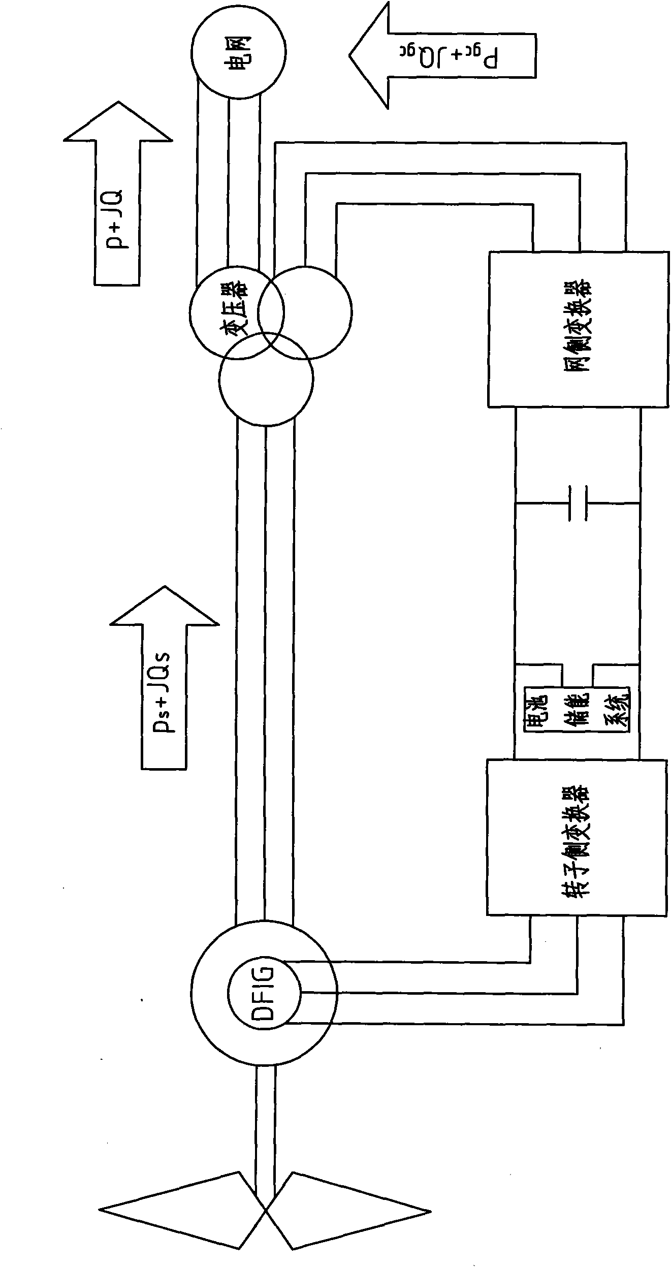
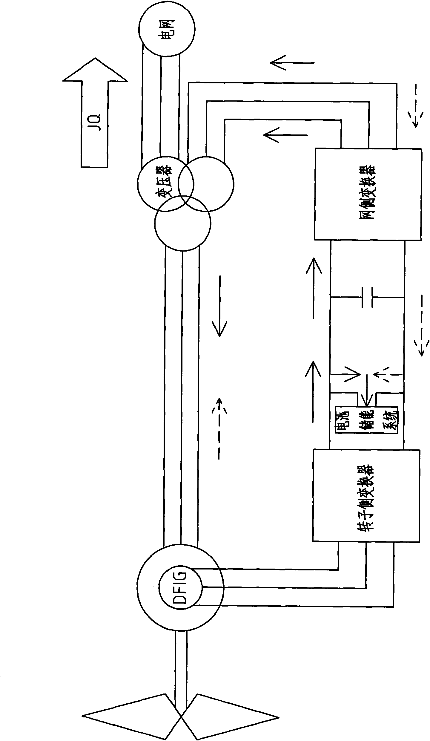
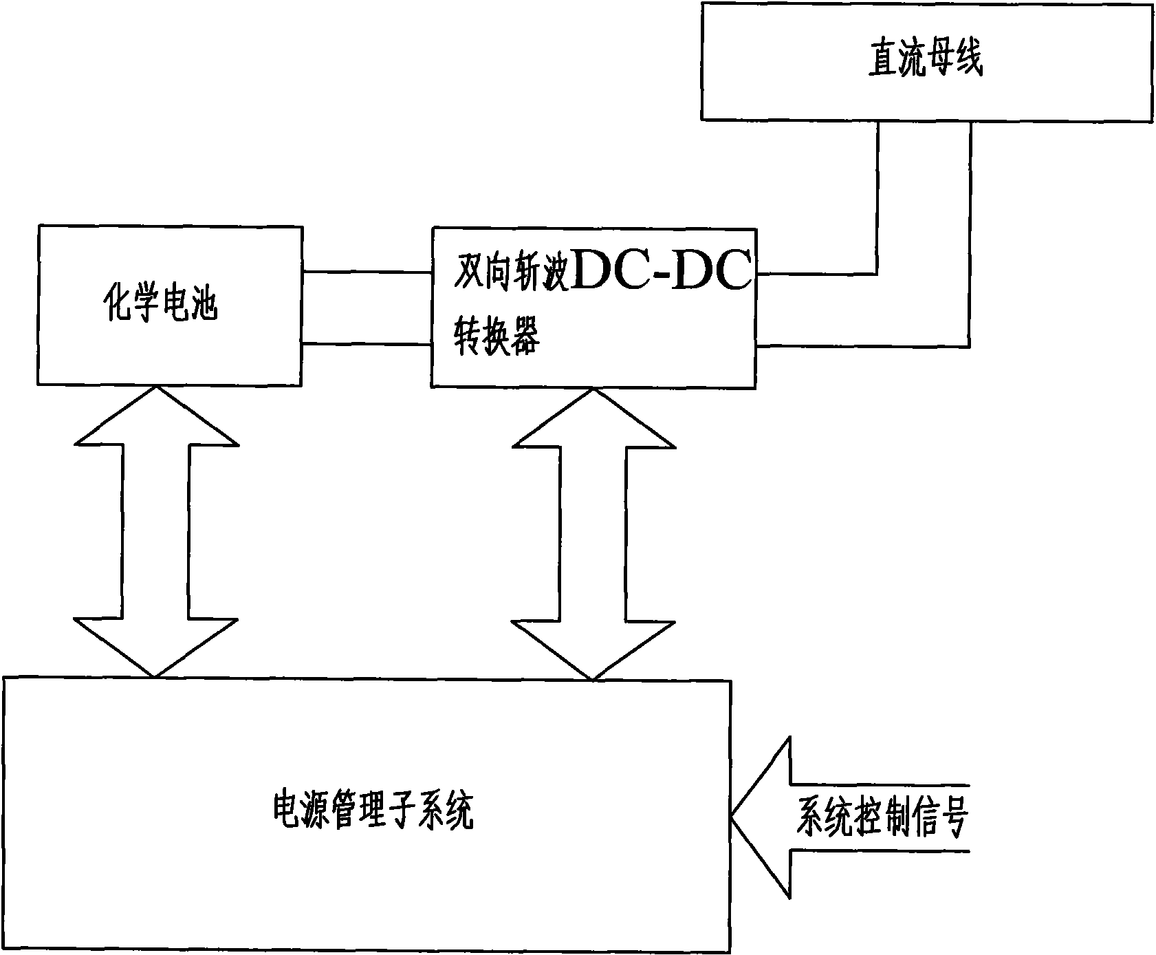
[0014] Such as Figures 1 to 3 As shown, an energy storage method for a doubly-fed converter, the doubly-fed converter includes a rotor-side converter and a grid-side converter, the DC terminal of the rotor-side converter is connected to the DC terminal of the grid-side converter, The AC end of the rotor-side converter is connected to the rotor of the double-fed generator set, and the AC end of the grid-transfer converter is connected to the stator of the double-fed generator set, and the stator of the double-fed generator set is connected to the power grid through a transformer; The feature is that a battery energy storage system is installed between the rotor-side converter and the grid-side converter, and when overcurrent and overvoltage on the rotor side are detected, the main control unit of the system controls the reverse rotation of the rotor-...


PUM


Abstract

The invention discloses an energy storage method for a double-feed current transformer. The double-feed current transformer comprises a rotor-side converter and a grid-side converter; the direct current end of the rotor-side converter is connected with the direct current end of the grid-side converter; the alternating current end of the rotor-side converter is connected with a rotor of a double-feed generating set; the alternating current end of the grid-side converter is connected with a stator of the double-feed generating set; and the stator of the double-feed generating set is connected with a power grid through a transformer. The method is characterized by comprising the following steps of: arranging an energy storage battery between the rotor-side converter and the grid-side converter, controlling the inversion of the rotor-side converter under the condition that over-current and over-voltage of the rotor side are detected, quickly charging the energy storage battery, storing the energy, and meanwhile providing current required for maintaining excitation of the stator side and providing reactive compensation for the power grid by the grid-side converter so as to provide support for voltage drop of the power grid; and for direct current component and over-current of the stator side due to imbalance, controlling the grid-side converter to store the direct current energy into the energy storage battery.

Description

technical field [0001] The invention relates to the field of electric power systems, in particular to the energy storage and grid connection technology of megawatt-level double-fed wind power generating sets. Background technique [0002] The known technology is that in the case of grid voltage drop, the doubly-fed induction generator in the wind turbine will cause overcurrent on the rotor side, and at the same time the rapid increase of the rotor side current will cause the DC side voltage of the rotor excitation converter to increase, and the generator excitation The current and active and reactive power of the converter will oscillate. This is because the stator flux linkage of the doubly-fed induction generator cannot follow the sudden change of the stator terminal voltage when the grid voltage drops instantaneously, thus generating a DC component. Due to the reduction of the integral, the stator flux linkage hardly changes, while the rotor Continued rotation will gener...

Claims


Application Information

Patent Timeline
Patent Type & Authority Applications(China)
IPC IPC(8): H02J3/38H02J15/00H02J7/00H02J3/18
CPCY02E40/30
Inventor 阮海明
Owner SHENZHEN CLOU ELECTRONICS
Learn More