Variable-temperature injection mould circulating system
A circulatory system and injection mold technology, applied in the field of circulatory system for controlling the temperature of plastic molds, can solve the problems of poor product accuracy, high polymer melt viscosity, and unavoidable internal stress.
- Summary
- Abstract
- Description
- Claims
- Application Information
AI Technical Summary
Problems solved by technology
Method used
Image

Examples
Embodiment Construction
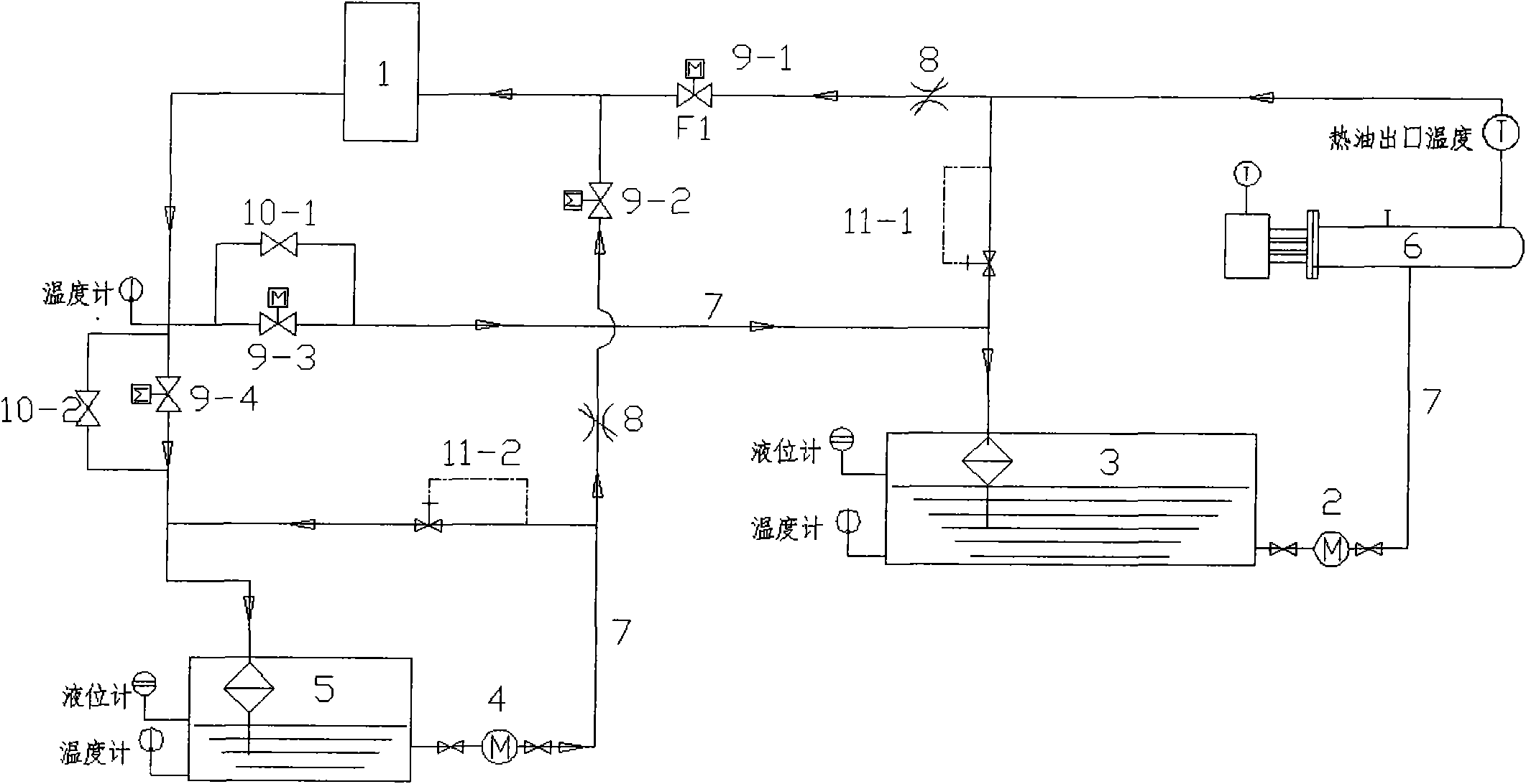
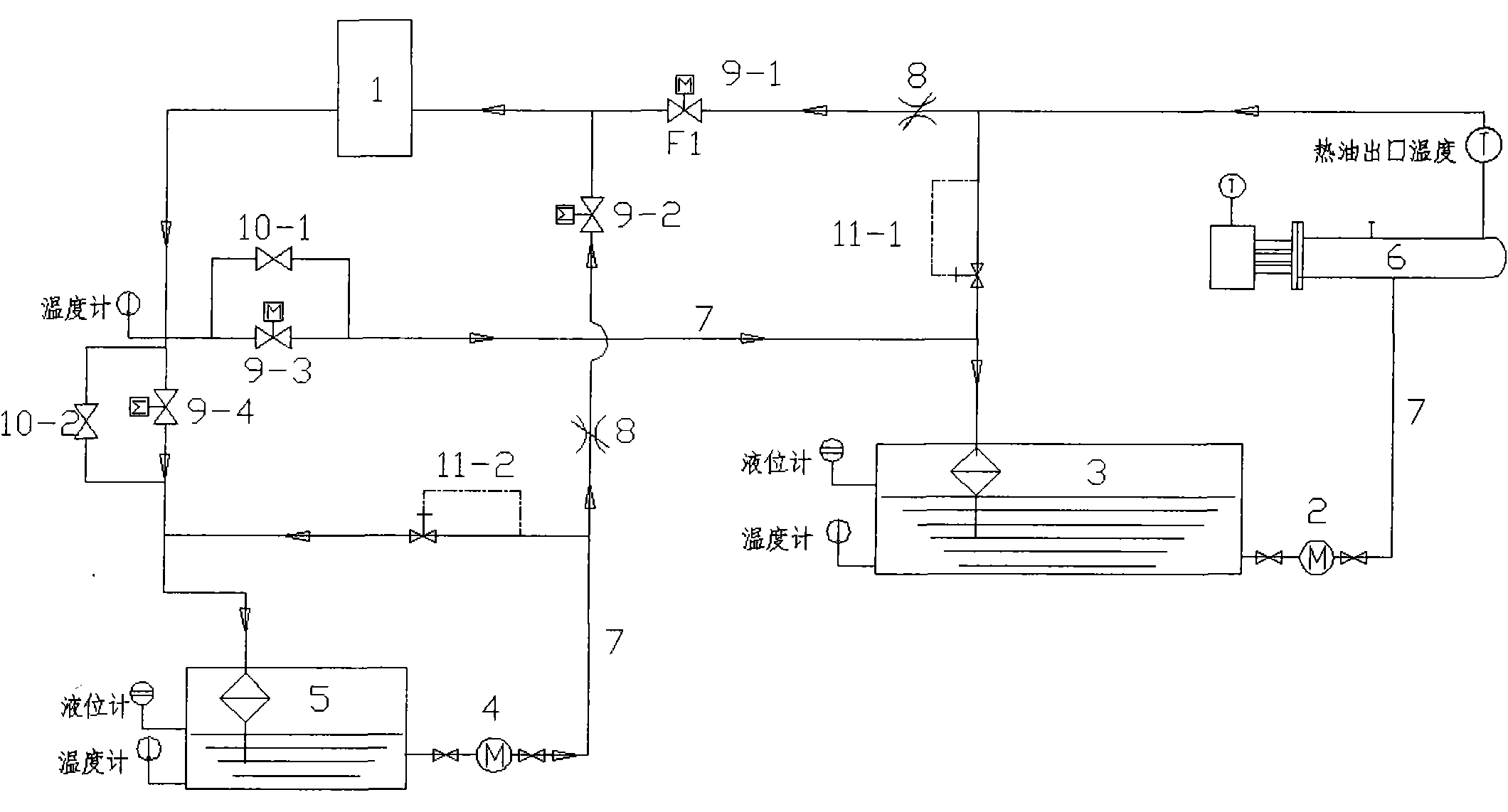
[0012] Depend on figure 1 As known, the present invention consists of heat equipment 1, thermal oil pump 2, thermal oil storage tank 3, cold oil pump 4, cold oil storage tank 5, electric heater 6, flow regulating valve 8, solenoid valve 9, manual control valve 10 and pressure The regulating valve 11 is composed, and the various components are connected by selecting high-temperature-resistant and high-pressure oil pipes 7 of corresponding specifications. The initial state of the system is that the solenoid valves 9-1 and 9-2 are closed, the hot oil pump 2 and the cold oil pump 4 are started, and the cooling water of the electric heater 6 and the cooling water pipe is in a normal working state, because the solenoid valve 9- 1, 9-2 is in the closed state, when the oil pressure of the oil pump reaches the set pressure of the pressure regulating valve 11 0.2MPa, the hot oil and cold oil will automatically flow back to the hot oil storage tank 3 and the cold oil storage tank through...
PUM
 Abstract
Description
Claims
Application Information
 - R&D
- Intellectual Property
- Life Sciences
- Materials
- Tech Scout
- Unparalleled Data Quality
- Higher Quality Content
- 60% Fewer Hallucinations
Browse by: Latest US Patents, China's latest patents, Technical Efficacy Thesaurus, Application Domain, Technology Topic, Popular Technical Reports.
© 2025 PatSnap. All rights reserved.Legal|Privacy policy|Modern Slavery Act Transparency Statement|Sitemap|About US| Contact US: help@patsnap.com