Centrifugal fly claw ratchet wheel braking locker and contact net compensation device

A catenary compensation, flying claw ratchet technology, applied in overhead lines and other directions, can solve the problems of heavy weight, poor locking reliability, large volume, etc., and achieve the effect of simple structure and reliable use

Inactive Publication Date: 2010-11-24
YANGZHOU DONGFANG HANGER FRAME CO LTD
View PDF7 Cites 9 Cited by
  • Summary
  • Abstract
  • Description
  • Claims
  • Application Information

AI Technical Summary

Problems solved by technology

Its disadvantages are: the device is large in size, heavy in weight, complex in structure and long in braking distance.
Its disadvantages are: the device also has a long length, the brake is easy to fail, and the locking reliability is poor.

Method used


Image

  • Centrifugal fly claw ratchet wheel braking locker and contact net compensation device
  • Centrifugal fly claw ratchet wheel braking locker and contact net compensation device
  • Centrifugal fly claw ratchet wheel braking locker and contact net compensation device

Examples


Embodiment 1

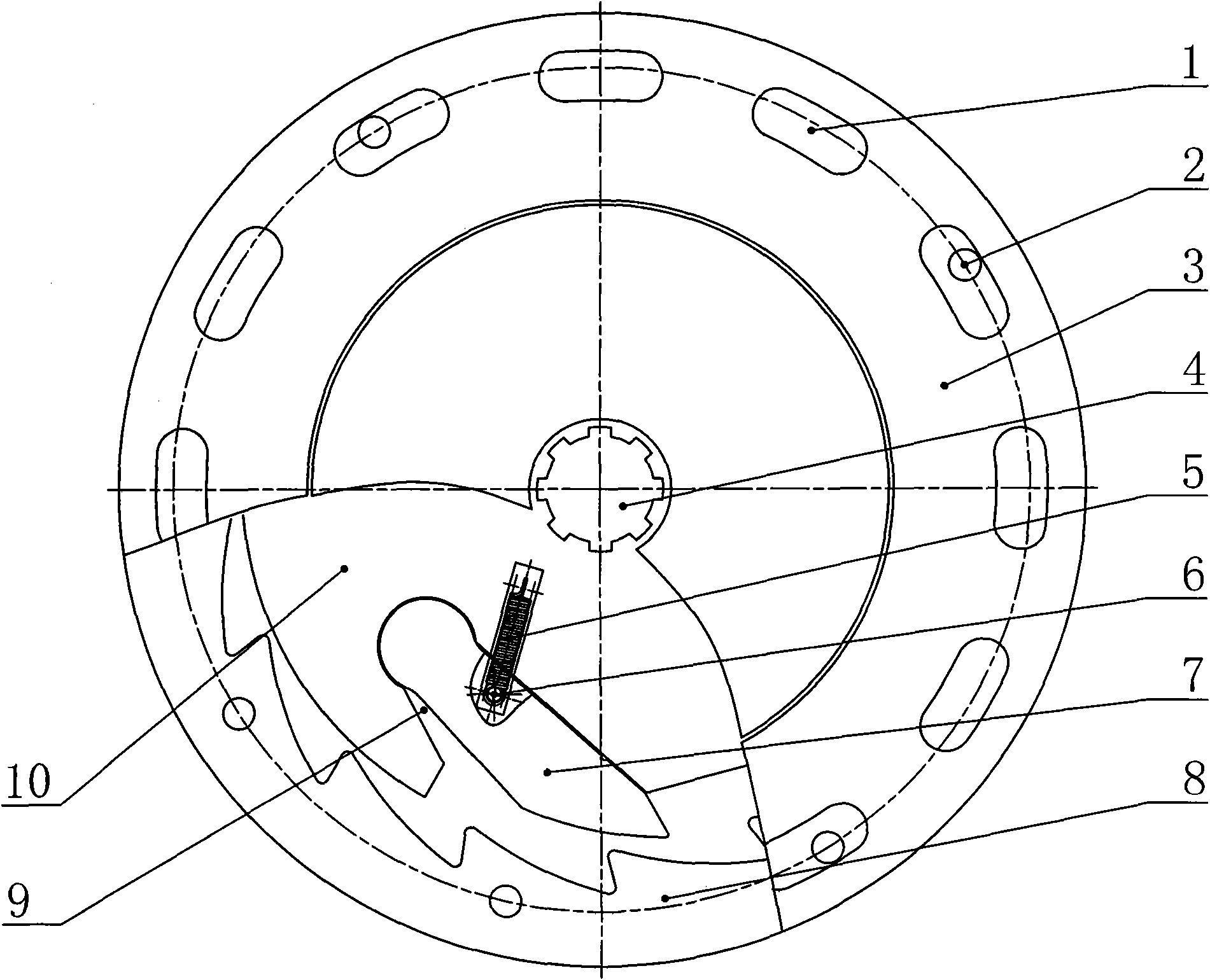
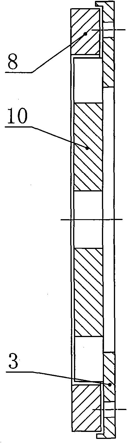
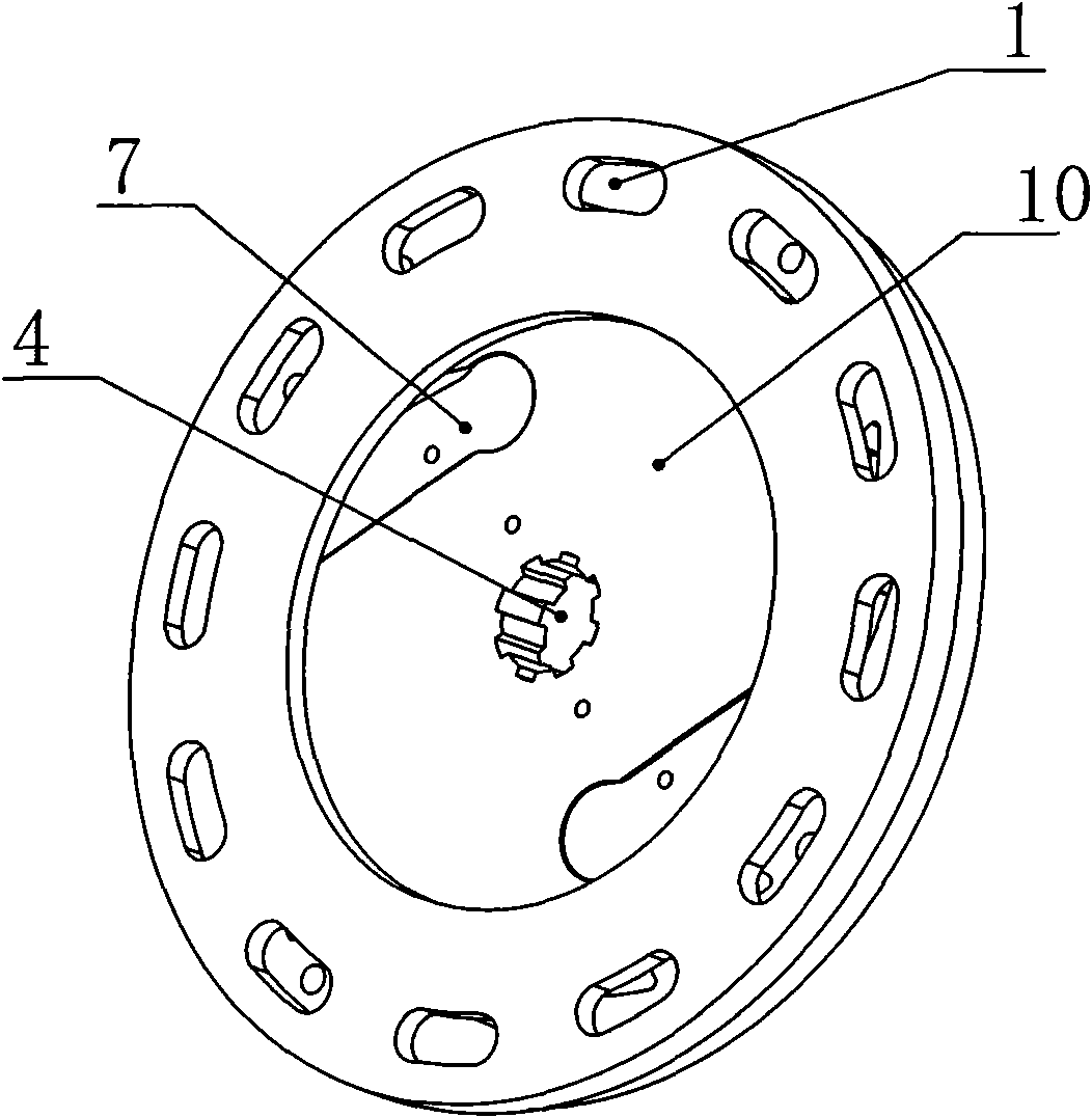
[0033] Such as Figure 1-4 As shown, it is a centrifugal fly paw ratchet brake locker, its structure mainly includes an internal tooth ratchet 8, a fly pawl 7 and a flywheel 10, the internal tooth ratchet 8 is set on the flywheel 10, and there is a gap between the two Clearance, the outer circumference of the flywheel 10 is symmetrically provided with two flying claw grooves 9 along the center of the flywheel shaft, the flying claws 7 are inserted into the flying claw grooves 9, and there is a gap between the flying claws 7 and the flywheel 10 to drive the flying claws to shrink. Elastic mechanism in claw groove, this elastic mechanism is extension spring 5, is provided with extension spring fixing screw 6 on fly claw 7, is provided with extension spring installation groove on flywheel 10, extension spring 5 one ends are fixed in extension spring installation groove, and the other One end is connected to the extension spring fixing screw 6, and the end of the flying claw 7 cor...

Embodiment 2

[0037] Such as Figure 5 As shown, it is a catenary compensation device, including a constant tension spring compensation device 20, on the main shaft 18a of the constant tension spring compensation device 20, a centrifugal fly paw ratchet brake locker 17 as in embodiment 1 is fixedly installed, the The internal tooth ratchet of the centrifugal fly paw ratchet brake locker 17 is fixedly connected to the side plate 21 of the constant tension spring compensation device, and the flywheel of the centrifugal fly pawl ratchet brake locker 17 is connected to the main shaft of the constant tension spring compensation device 18a is fixedly connected.

Embodiment 3

[0039] Such as Figure 6-7 As shown, it is a catenary pendant compensation device equipped with a centrifugal flying claw ratchet brake locker as shown in Embodiment 1. Its structure mainly includes a bracket 11 arranged on an electric pole 12. The rotating main shaft 18 is provided with a large-diameter tension wire pulley 16 and one or two small-diameter tension wire pulleys 19 linked to each other on the main shaft 18. The large-diameter tension wire pulley 16 is wound with a steel wire rope 13a, and the lower end of the steel wire rope 13a is suspended A pendant 14 is hung, a small-diameter tensioning wire wheel 19 is wound around a steel wire rope 13b with a connecting wire or a load-bearing cable, and the centrifugal flying claw ratchet brake locker 17 is arranged on the main shaft 18. The centrifugal flying claw ratchet system The internal tooth ratchet 8 of the dynamic locking device 17 is connected with the fixed outer plate of the bracket 11, and the flywheel 10 of t...


PUM


Abstract

The invention discloses a centrifugal fly claw ratchet wheel braking locker in the technical field of contact nets, comprising an inner tooth ratchet wheel, a fly claw and a fly wheel, wherein the inner tooth ratchet wheel is sleeved on the fly wheel, the outer circumference of the fly wheel is at least provided with a fly claw slot, and the fly claw is plugged in the fly claw slot; an elastic mechanism for driving the fly claw to be contracted in the fly claw slot is arranged between the fly claw and the fly wheel; and the end part of the fly claw corresponds to ratchet teeth of the inner tooth ratchet wheel. After the line of a contact net is suddenly broken, the fly wheel is quickly forced to brake. The invention also discloses a contact net compensation device with the centrifugal fly claw ratchet braking locker, comprising a rotatable spindle arranged on a bracket, wherein a large-diameter tensioning thread wheel and a small-diameter thread wheel which are mutually linked are arranged on the spindle; a steel wire rope for suspending a sliding weight is wound outside the large-diameter tensioning thread wheel, and a steel wire rope connected with a lead or a carrier cable is wound outside the small-diameter tensioning thread wheel; the inner tooth ratchet wheel is fixedly connected with the bracket; and the fly wheel is fixedly connected with the spindle. The invention can thoroughly avoid the clamping and the eccentric wear of the steel wire ropes.

Description

technical field [0001] The invention relates to a catenary compensation device for an electrified railway, in particular to a broken line brake locker and a catenary compensation device with the brake locker. Background technique [0002] At present, the wires and catenary cables of the catenary compensation devices for electrified railways all over the world are connected with various types of compensation devices by steel wire ropes. The gravity of the heavy weight or the spring force of the spring compensation device will form a strong pulling force, which will instantly pull the broken catenary to one side of the compensation device, causing a vicious accident of broken wires and broken wires, forcing the train to stop running. [0003] A side brake ratchet tension compensation device for electrified railway catenary is disclosed in the Chinese patent database, its publication number: CN101695907, application date: 2009.10.30, publication date: 2010.04.21; The movable s...

Claims


Application Information

Patent Timeline
Patent Type & Authority Applications(China)
IPC IPC(8): B60M1/26
Inventor 帖荣俊潘英吴利群帖广宏陈勇吴承宸
Owner YANGZHOU DONGFANG HANGER FRAME CO LTD
Why Eureka
Try Eureka