Vehicle exhaust waste heat generating system

A technology for waste heat power generation and automobile exhaust, which is applied in the directions of electromechanical devices, electrical components, and electric components, which can solve the problems of heat loss and low thermal efficiency, and achieve the effect of small occupied space, improved thermal efficiency, and compact structure.

Inactive Publication Date: 2010-11-24
SOUTH CHINA UNIV OF TECH
View PDF7 Cites 7 Cited by
  • Summary
  • Abstract
  • Description
  • Claims
  • Application Information

AI Technical Summary

Problems solved by technology

[0002] In the use of automobiles, the automobile engine, as the heart of the automobile, is the source of automobile power and the direct consumer of fuel, but at present, the thermal efficiency of most automobile engines is very low (20%-30%), and the heat generated by the engine is overwhelming Part of it is directly discharged into the atmosphere in the form of waste heat from automobile exhaust. This, on the one hand, causes a large amount of heat loss, and on the other hand, it puts increasing pressure on the already severe climate.
In recent years, the state has been advocating the construction of an energy-saving and emission-reducing society. These cars with low thermal efficiency run counter to the construction of an energy-saving and emission-reducing society. At present, there is no effective system for generating electricity by using the waste heat of automobile exhaust

Method used


Image

  • Vehicle exhaust waste heat generating system
  • Vehicle exhaust waste heat generating system
  • Vehicle exhaust waste heat generating system

Examples


Embodiment Construction

[0016] The present invention will be further described in detail below in conjunction with the embodiments and the accompanying drawings, but the embodiments of the present invention are not limited thereto.

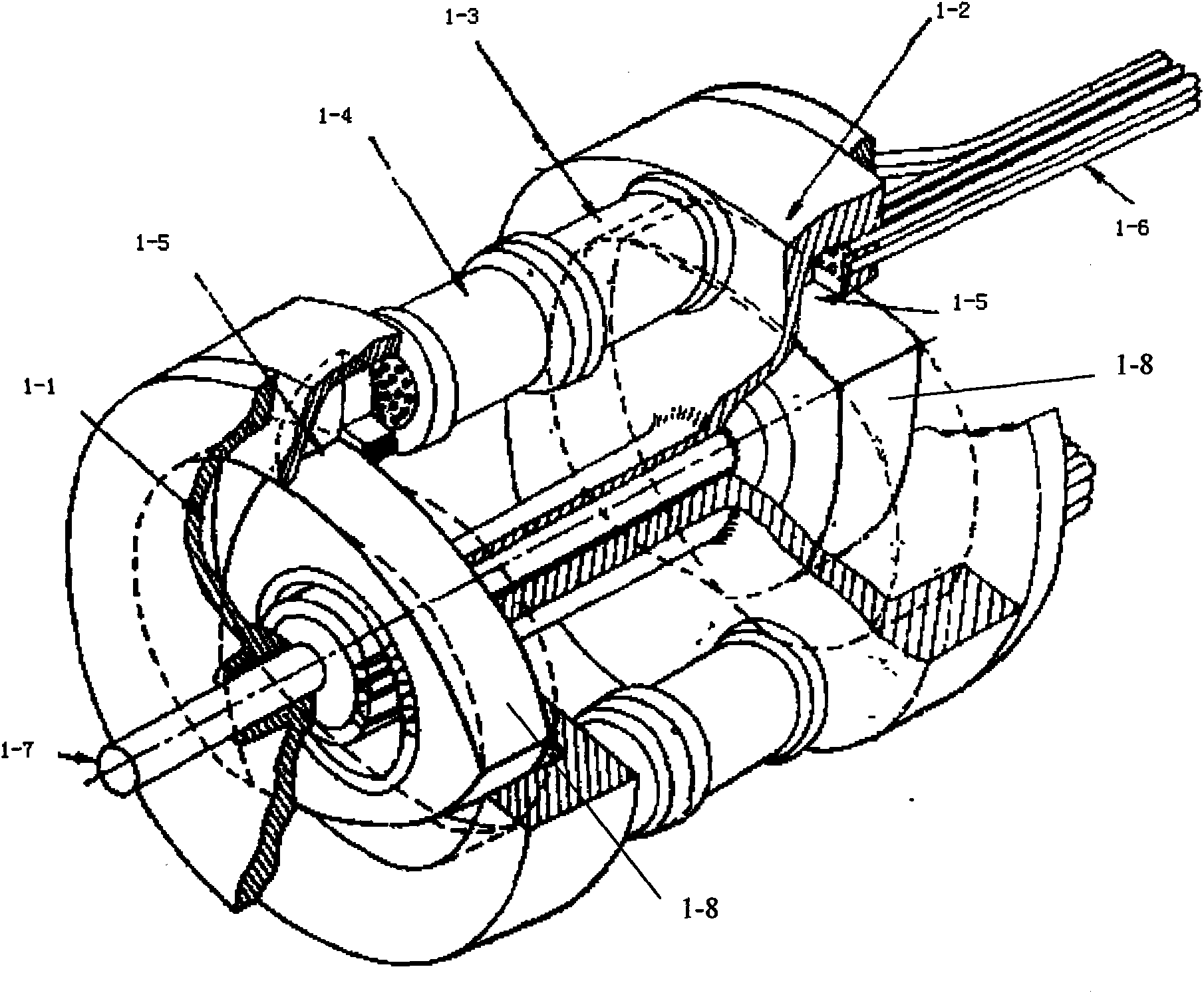
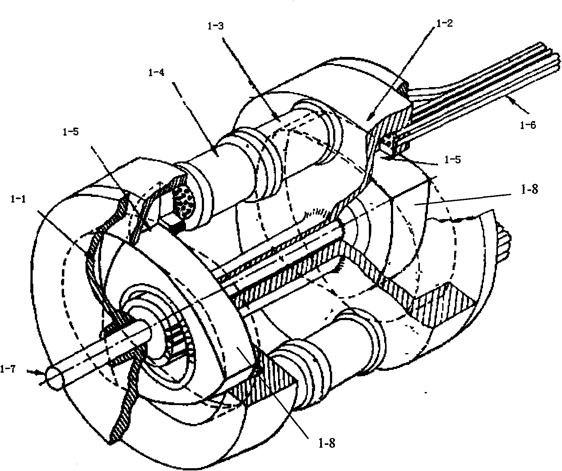
[0017] In this embodiment, an automobile exhaust waste heat power generation system includes a connected heat engine unit and a flywheel battery unit, wherein the structure of the heat engine unit is as follows figure 1 As shown, it includes cooling chamber 1-1, expansion chamber 1-2, regenerator 1-3, water-cooled heat exchanger 1-4, heating air pipe 1-6 and mechanical work output shaft 1-7, cooling chamber 1-1 The cooling chamber 1-1 and the expansion chamber 1-2 are respectively arranged at the two ends of the mechanical work output shaft 1-7, and the inside of the cooling chamber 1-1 and the expansion chamber 1-2 are respectively connected by the rotor 1-8. Each is divided into three independent air chambers, and the corresponding two air chambers in the cooling chamb...


PUM


Abstract

The invention provides a vehicle exhaust waste heat generating system, comprising a heat engine unit and a flywheel battery unit which are connected; a cooling chamber and an expanding chamber in the heat engine unit are respectively arranged at the two ends of a mechanic work output shaft, the interiors of the cooling chamber and the expanding chamber are respectively divided into three independent air chambers by rotors, two corresponding air chambers in the cooling chamber and the expanding chamber are connected by virtue of a water cooling heat exchanger and a heat regenerator, and a heating air tube is connected with the expanding chamber; the rotary shaft in the flywheel battery unit is connected with the mechanic work output shaft, the two ends of the rotary shaft are respectively provided with a bearing, a stator coil is arranged at the middle part of the rotary shaft, the two sides of the stator coil are respectively provided with a flywheel rotor provided with a permanent magnet, and the rotary shaft, the bearing, the flywheel rotor and the stator coil are respectively arranged in a battery case. The invention can effectively solve the problem that massive thermal is dissipated as vehicle exhaust is directly discharged, vehicle thermal efficiency is improved in large scale and energy conservation and emission reduction of vehicle is achieved while discharge of massive waste gas is reduced.

Description

technical field [0001] The invention relates to the recycling technology of automobile tail gas, in particular to a waste heat power generation system of automobile tail gas. Background technique [0002] In the use of automobiles, the automobile engine, as the heart of the automobile, is the source of automobile power and the direct consumer of fuel, but at present, the thermal efficiency of most automobile engines is very low (20%-30%), and the heat generated by the engine is overwhelming Part of it is directly discharged into the atmosphere in the form of waste heat from automobile exhaust, which, on the one hand, causes a large amount of heat loss, and on the other hand, puts increasing pressure on the already severe climate. In recent years, the state has been advocating the construction of an energy-saving and emission-reducing society. These cars with low thermal efficiency run counter to the construction of an energy-saving and emission-reducing society. At present, ...

Claims


Application Information

Patent Timeline
Patent Type & Authority Applications(China)
IPC IPC(8): F02G5/02H02K7/02
CPCY02T10/166Y02E60/16Y02E20/14Y02T10/12
Inventor 谢小鹏牛高产贾尚雨刘粲
Owner SOUTH CHINA UNIV OF TECH
Why Eureka
Try Eureka